SqNode Objects 
SqNode objects are the connected nodes on a SynqNet
network. SynqNet supports up to 32 nodes supporting up to 32 motors on
one SynqNet network.
Configuration Attributes: "Config"
Tab Page
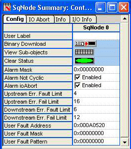
User Label – User-defined label for the object.
Binary Download – Downloads a binary file to
the node which allows communication for normal operation between the controller
and the node. Unless the Drive vendor has already installed the .sff file
at the factory, an appropriate binary file will need to be downloaded.
To determine which .sff file is appropriate for your node, please refer
to the Node FPGA Images: Identification Table. Multiple files may be downloaded to multiple
nodes/drives. See Downloading Binary Files for more information.
View Sub-objects – Shows all sub-objects for
this object. For more information, see Object Summary
Windows.
Clear Status – Clears node CRC errors on all
ports, clears node Packet errors, clears node ioAbort state, and resets
SqNode events.
Alarm Configuration Attributes
The Alarm configuration attributes configure the trigger
conditions for the Node Alarm output bit. See MPISqNodeConfigAlarm
for more information.
Alarm Mask – One bit per drive/motor. Configures
the node alarm output to trigger when the Amp Fault dedicated input of
the motor is TRUE.
Alarm Not Cyclic – Specifies whether or not
a node can receive an alarm when it is not in cyclic mode. When checked,
a node alarm can be asserted in any mode. Otherwise, a node alarm can
only be asserted in cyclic mode.
Alarm ioAbort – Specifies the effect an IO
abort will have on the node alarm output. When checked, an I/O abort will
trigger a node alarm.
Node Packet Error Rate Attributes
The following attributes specify the limit conditions
for SynqNet node packet rate errors. See MPISqNodeConfigPacketError
for more information.
Upstream Err. Fault Limit – Packet error rate
limit on the IN port to generate a fault.
Upstream Err. Fail Limit – Packet error rate
limit on the IN port to generate a failure.
Downstream Err. Fault Limit – Packet error rate limit on the OUT port to generate a fault.
Downstream Err. Fail Limit – Packet error rate
limit on the OUT port to generate a failure.
User Fault Configuration Attributes
The User Fault configuration attributes specify the
trigger conditions for a user fault. See MPISqNodeConfigUserFault
for more information.
User Fault Address – The controller address
to trigger off of.
User Fault Mask – A bit mask ANDed with the
value at the controller address.
User Fault Pattern – A bit pattern compared
to the masked value at the controller address. When the masked value equals
the pattern, the user trigger is TRUE.
Configuration Attributes: "IO Abort"
Tab Page
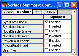
The I/O Abort configuration attributes
specify the trigger conditions for a user fault. See MPISqNodeConfigIoAbort
for more information.
SynqLost Enable – When checked, the controller
will generate an I/O Abort Action when a SynqNet node drops out of SYNQ
(cyclic) mode to SYNQ_LOST mode.
SynqLost Invert – When checked, the controller
will invert the trigger polarity.
NodeDisable Enable - When checked, the controller
will shutdown the node via IoAbort when the node disable is active.
NodeDisable Invert – Inverts trigger polarity
of the signal. When not checked, it will have normal polarity. If checked,
it will have inverted polarity.
PowerFault Enable – An input bit to the SynqNet
node. The power fault circuit is node-specific, but is usually connected
to an analog power monitor. Typically, when the DAC power or other analog
component power is either too high or drops below a threshold, the power
fault is triggered.
PowerFault Invert – Inverts trigger polarity
of the signal. When not checked, it will have normal polarity. If checked,
it will have inverted polarity.
User Fault – The controller will generate an
I/O Abort Action when the User Fault is triggered. The conditions for
generating a User Fault are configured on the Config tab page.
Configuration Attributes: "Info"
Tab Page
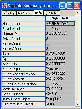
Node Name – A string that represents the SynqNet
node type. See MPISqNodeInfoId.
Exact Match – "Yes" when all ID components
have been matched to a supported configuration. See MPISqNodeInfoId.
Unique ID – The SynqNet node manufacturer determines
this unique value to track a single product. See MPISqNodeInfoId.
Drive Count – The number of drives interfaces
that the SynqNet node supports.
Motor Count – Number of motors mapped to the
node.
Motor Offset – The starting number for the first
motor on the SynqNet node. Example: If Node 0 has three motors (Motor
0-2), then the Motor Offset for Node 1 will be 3 because Motor 3 is the
next available motor.
Type – This is a unique identification number
that can be used to identify the type and manufacturer of the node.
Option – The product option code within a product
series. See MPISqNodeInfoId.
Switch ID – If a node/drive has an address switch
on its faceplate, Switch Id will be the value to which the switch is set.
If an ID switch is not supported by the node, this value will be set to
-1 (0xFFFFFFFF). See MPISqNodeInfoId.
FPGA Type – There are two FPGA Types that are
used, Boot and Runtime. For more information about these FPGA types, please
see the Binary Images section under SynqNet
Technology. See MPISqNodeFpgaType.
Boot
- The FPGA that is initially used when the SynqNet network is initialized
for the
first time. It enables the node to communicate with the controller. A
runtime
image will need to be downloaded
before any motors can move.
Runtime
- The FPGA that is used for normal operation.
FPGA Vendor/Device – The unique indentification
number of the FPGA. For more information, please refer to the Node FPGA Images: Identification Table. See MPISqNodeInfoFpga.
FPGA Version – The version of the FPGA. See
MPISqNodeInfoFpga.
FPGA Default Version – Indicates if the default
version of the SqNode FPGA image is loaded on this node. See MPISqNodeInfoFpga.
Model Number – The model number of the node
(if available). See MPISqNodeInfoId.
Serial Number – The serial number of the node
(if available). See MPISqNodeInfoId.
In Port Next Object – Name of the next network object connected to this object on the In Port.
Out Port Next Object – Name of the next object connected to this object on the Out Port.
Configuration Attributes: "Info" Tab Page
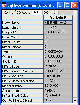
Digital In – The number of digital inputs on a SynqNet node. See MPISqNodeInfoIo.
Digital Out – The number of digital outputs on a SynqNet node. See MPISqNodeInfoIo.
Analog In – The number of analog inputs on a SynqNet node. See MPISqNodeInfoIo.
Analog Out – The number of analog outputs on a SynqNet node. See MPISqNodeInfoIo.
Segment Count – The total number of segments on a SynqNet node. See MPISqNodeInfoIo.
Max Wait – This is the maximum amount of time between when the output bit is set in software and the hardware state takes effect. See MPISqNodeInfoIo.
Status Attributes: "Status" Tab Page
SqNode status attributes display read-only data of each
node. These are non-configurable.
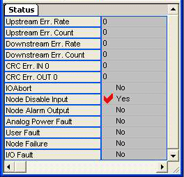
Packet Errors
For more information on Packet Error Rates and Counters,
see MPISqNodeStatusPacketError.
Upstream Err. Rate – Number of upstream packet
errors per cycle.
Upstream Err. Count – Number of upstream packet
errors.
Downstream Err. Rate – Number of downstream
packet errors per cycle.
Downstream Err. Count – Number of downstream
packet errors.
CRC Errors
For more information on the CRC Error Counters, see
the CRC Error Counters
section.
CRC Err. IN 0 – CRC error counter for the IN
0 port.
CRC Err. OUT 0 – CRC error counter for the
OUT 0 port.
Events
For more information concerning the following Events,
see MPIEventType.
IO Abort – Generated when the node I/O Abort
is activated. See MPIEventTypeSQNODE_IO_ABORT.
Node Disable Input –
Generated when the Node Disable input signal transitions from inactive
to active. See MPIEventTypeSQNODE_NODE_DISABLE.
Node Alarm Output – Generated when the node
alarm output signal transitions from inactive to active. See MPIEventTypeSQNODE_NODE_ALARM.
Analog Power Fault – Generated when the node's
power failure input bit transitions from inactive to active. See MPIEventTypeSQNODE_ANALOG_POWER_FAULT.
User Fault – Generated when the node's user
configurable fault is triggered. See MPIEventTypeSQNODE_USER_FAULT.
Node Failure – Generated when a node's upstream
or downstream packet error rate counters exceed the failure limit. To
recover from a node failure, the network must be shutdown and reinitialized.
See MPIEventTypeSQNODE_NODE_FAILURE.
Downloading Binary Files
| |
Follow the procedure below to download binary files to SynqNet nodes. |
| |
- Click on the Binary Download button for the node on the SqNode Summary.

- If you are downloading the same file(s) to multiple nodes, then you can select the nodes (Ctrl + click) and click the Binary Download button.
NOTE: All nodes in the selection must already have the same default FPGA file in order for the Binary Download button to be enabled.

- After clicking the Binary Download button, the “Download Binary Image To SqNode(s)” dialog box pops up. In this dialog box, it is possible to select multiple files to download to the node. One FPGA file can be selected, as well as (possibly multiple) Drive Processor firmware files. The number of drive processors is dependent on the type of node. A node with two drive processors is shown below.
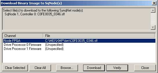
If the file is labeled “Unspecified”, then no file will be downloaded to that item. To specify a file for an item, click on the item to select it and then click on the Browse button. The default FPGA file will usually be pre-specified for the FPGA item. To “unspecify” a file for an item, select the item in the list and click the Clear Selected button. Click the Clear All button to “unspecify” a file for every item.
- After all the binary files are specified, click the Download button. The “Downloading Firmware” dialog box will pop up:
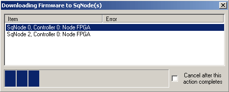
The item selected in the list indicates which item is currently being downloaded. The status bar at the bottom indicates the download progress for the current item. If there is no error for any item in the list, then the dialog box will close automatically. Otherwise, an error message will be displayed in the Error column. The dialog box is left open to allow the user to read the error. Click on the “Close” button to exit the dialog box.
Downloading cannot be interrupted once it starts, but it is possible to cancel downloading after the current download is complete. To cancel the download, click on the “Cancel after this action completes” checkbox.
- Once the download is complete and the “Downloading Firmware to SqNode(s)” dialog box is closed (either manually or automatically), close the “Download Binary Image To SqNode(s)” dialog box.
|
|
