The next step is to set up the hardware of the
system based upon the selected topology. Currently, SynqNet supports
the following three topologies:
For more information about the various topolgies,
please see the Node,
Cable, Motor, Drive Addressing section under the SynqNet Technology
page.
Cable
Connections: Controller to Node(s)
The type of cables needed to connect the controller
to the node(s) will vary based upon the type of controller, the
particular hardware features, and the type of nodes you are using
in the SynqNet Network. However, regardless of these variables,
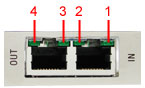
the cables will be wired the same way. For example, you will always
connect a cable from an OUT port and into an IN port. The following
diagram will clearly illustrate this connection pattern. For more
information about cables and connectors, see the SynqNet
Hardware section.
Types of Connectors and Cables
Depending on the type of SynqNet ports (RJ45
or Micro-D) on your Controller and Drive, you will need to use
one of the corresponding cables to connect them to each other.
Please see the Cables
section for a list of the various cables.
The following table lists some of the common
connectors and their matching cables.
|
Feature
|
Connector
|
Cable
|
| Controller I/O |
|
N/A |
|
|
N/A
|
|
SynqNet
|
|
|
|
|
|
Power On Nodes and Check LEDs
After all of the nodes have been connected with
the proper cables, power-up the system. To verify that the Nodes
have been connected correctly and that each node is receiving
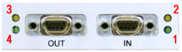
a network and power signal, inspect the LEDs at each connector.
Each controller will have four green
LEDs:
Each node will have four green LEDs:
| |
Node LEDs on
the RMB-10V2-SynqNet
- LED1 - Link Activity
- LED2 - Node State
- LED3 - Link Activity
- LED4 - Repeater
- LED5 - FPGA
- LED6 - FPGA Boot Status
For more information, please see the Node LEDs section.
|
The RMB-10V2-SynqNet is shown above. |