Controller LEDs
SynqNet
| CAN
See Also: Node LEDs
SynqNet
SynqNet controller LEDs will BLINK to indicate a fault (or undiscovered network). A controller with no blinking LEDs is in normal cyclic operation (without faults). Each SynqNet port has two LEDs. And each LED has a particular function, which is described in further detail below.
Each controller will have four green LEDs:
|
![]() |
|
LED
|
Port
|
Meaning
|
Controlled by
|
State
|
|
LED1
|
OUT
|
Link Activity
|
PHY
|
ON = link active
|
|
OFF = link inactive
|
||||
|
LED2
|
OUT
|
Network Activity
|
MAC
|
ON = Tx and Rx active
(cyclic phase) |
|
BLINK = Tx only active
(discovery phase) |
||||
|
OFF = Idle (shutdown phase), or during
a network reset.
|
||||
|
LED3
|
IN
|
Link Activity
|
PHY
|
ON = link active
|
|
OFF = link inactive
|
||||
|
ON = Tx
|
||||
| LED4 | IN | Network Activity | MAC |
ON = Tx and Rx active
(cyclic phase) |
|
BLINK = Tx only active
(discovery phase) |
||||
|
OFF = idle (shutdown phase), or during
a network reset.
|
LED1 and LED3 = Link Activity
|
LED2 and LED4 = Network Activity
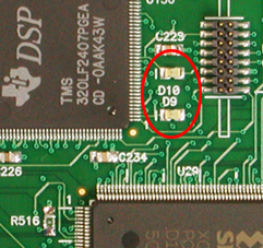
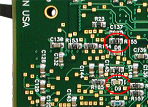
|
CAN
The XMP-CAN controllers have two green LEDs. These LEDs give a visual representation of the activity on the CAN network. The locations of the LEDs vary depending on the type of XMP-CAN controller. The photos and table below show the locations and meanings of each LED.
|
D9 = CAN 2 |
D8 = CAN 2 |
|
CAN1
|
CAN2
|
Code Executing
|
State
|
|
OFF
|
OFF
|
None
|
No power / No bootloader present
|
|
BLINK
|
ON
|
Bootloader
|
No firmware (waiting for firmware)
|
|
OFF
|
ON
|
Bootloader
|
Programming firmware
|
| ON | ON | Firmware |
No Configuration
|
| ON | OFF |
Bootloader present with valid firmware
|
|
| ON | Fast Blinking (0.25/sec) | Firmware |
CAN Bus Error
|
| ON | Slow Blinking (1/sec) | Firmware |
CAN Operational
|


