
|
|
| . |
Controller Objects
|
||||||||||||
|
![]()
WARNING! When using Motion Console with
multiple controller systems, make sure you know exactly which physical
controller is associated with which device index. Be sure to always verify
controller-to-device index relationships before commanding any motion.
The Controller Summary window lists Controller attributes in the tab pages: Actions, Config, Version, Stats, and Recorders.
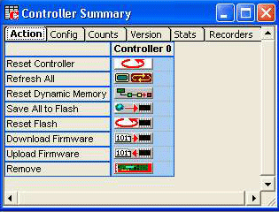
Reset – Resets the controller to the power-up configuration saved in flash memory.
Refresh – Refreshes display to reflect any external modifications.
FW Upload – Uploads Flash memory to the firmware file. See the Uploading Firmware section earlier in this chapter for more information.
FW Download – Downloads the firmware file to Flash memory. See the Downloading Firmware section earlier in this chapter for more information.
Reset Dynamic Memory – Returns the controller’s dynamic memory to the default values and re-initializes the SynqNet network. All dynamic configurations modified by the user will be lost.
Save All to Flash – Copies all configurations and network topology from the controller’s dynamic memory to flash memory. When the controller is reset or powered off/on, the flash configurations will be loaded into the controller’s dynamic memory.
Reset Flash – Returns the controller’s dynamic memory and flash memory to the default values and re-initializes the SynqNet network. All dynamic and flash configurations modified by the user will be lost.
Download Firmware – Downloads the firmware file to Flash memory. See the Downloading Firmware section earlier in this chapter for more information.
Upload Firmware – Uploads Flash memory to the firmware file. See the Uploading Firmware section earlier in this chapter for more information.
Remove – Removes controller from Motion Console controller list.
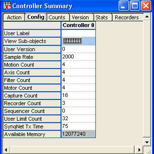
User Label – User-defined label for the object.
View Sub-objects – Shows all sub-objects for the Controller. For more information, see the View Sub-object section.
User Version – User defined version. See MPIControlConfig.
Sample Rate – Sample Rate (samples/sec). See MPIControlConfig.
MS Count – Number of enabled Motion Supervisor objects. See MPIControlConfig.
Axis Count – Number of enabled Axis objects. See MPIControlConfig.
Filter Count – Number of enabled Filter objects. See MPIControlConfig.
Motor Count – Number of enabled Motor objects. See MPIControlConfig.
Capture Count – Number of enabled Capture objects. See MPIMotorInfo
Recorder Count – Number of enabled Recorder objects. See MPIControlConfig.
User Limit Count – Number of enabled User Limit objects. See MPIControlConfig.
Sequence Count – Number of enabled Program Sequence objects. See MPIControlConfig.
SynqNet Tx Time – The time at which the SynqNet data is transmitted. The Tx Time value represents the percentage of the sample period. This should be set in such a way that the transmissions occur after the firmware has completed its foreground cycle. (0-100%).
For more information, see SynqNet Tx Time.
Available Memory – The amount of external memory available on the controller. The maximum value for Record Count and Axis Count is limited by the available memory.
The Counts page shows the number of allocated object in the controller memory:
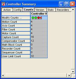
Pressing the “Modify Counts…” button will open the Dynamic and Enabled Object Counts window. From here you can change the number of objects allocated in the controller’ dynamic memory and the number of objects enabled. Changing the allocation will clear the controller’s dynamic memory and re-allocate the memory. Thus, all user modified configurations will be lost. It is a good idea to allocate all your objects first, before configuring any of them.
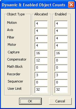
Tip: For best controller performance, only enable the objects you are actually using.
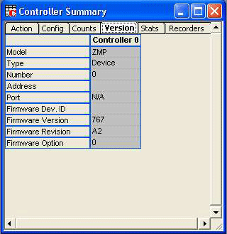
Model – They type of motion controller
Type – Currently either "Device" or "Client." See MPIControlInfoHardware.
Number – The device number of the controller on the bus.
Address – The device driver for "Device" type controllers, the IP address for "Client" type controllers.
Port – Port for "Client" type controllers only.
Firmware Dev. ID – Firmware Development ID.
Firmware Version – Firmware Version. See MPIControlInfoFirmware.
Firmware Revision – Firmware Revision. See MPIControlInfoFirmware.
Firmware Option – Firmware Option. See MPIControlInfoFirmware.
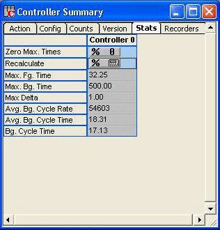
Zero Max. Times – Zeros the maximum foreground and background timers.
Recalculate – Triggers a recalculation of the timing statistics.
Max Fg. Time – Maximum foreground time in microseconds. Max Bg. Time– Maximum background time in microseconds.
Max Delta – Maximum Delta (samples/ background cycle).
Avg. Bg. Cycle Rate – Average interrupted background cycle rate (cycles/sec).
Avg. Bg. Cycle Time – Average interrupted background cycle time in microseconds.
Bg. Cycle Time – Uninterrupted background cycle time in microseconds.
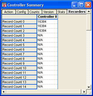
Record Count 0-63 – Number of data records per enabled data recorder object for a controller. The controller's recorder object handles collecting and buffering any data in controller memory. The enabled data recorders can collect up to a total of 32 addresses each sample. See MPIControlConfig.
| | | Copyright © 2001-2009 Motion Engineering |