|
|
| . |
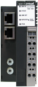
TSIO-1001; SynqNet Network Adapter
|
||||||||||||||||||||||||||||||||||||||||||||||||||||||||||||||||||||||||||||||||||||||||||||||||||||||||||||||||||||||||||||||
|
|
|
| Communication Interface Specifications | |
| Number of network nodes on a single bus | Max. 32 |
| Max. Number of slices per Network Adapter |
32 (Additional system power may be required) |
| LED Indicators | 1 green: LINK IN status indicator 1 green: CYCLIC status indicator 1 green: LINK OUT status indicator 1 green: REPEATER status indicator 1 green: FPGA status indicator |
| Bit Rate | 100M |
| Max. Number of I/O bits per Network Adapter |
Maximum IO |
| General Specifications | |
| System Power | Supply Voltage: 24Vdc nominal Voltage Range: 11~28.8Vdc |
| Power Dissipation | Nominal 24Vdc @ 100mA |
| Current for I/O Module | Max 5Vdc @ 1.5A |
| Isolation | Network to Logic: Isolation Logic to Field Power: Isolation Logic to System Power: No isolation |
| Field Power | Supply Voltage: 24Vdc nominal Voltage Range: 11~28.8Vdc |
| Current of Jumper Contacts | DC 10A maximum capacity |
| I/O Cables | Max. AWG 14 |
| Weight | 150g |
| Module Size |
42mm x 67mm x 95mm |
Pin |
In |
Out |
Color |
Standard pinout (NIC=MDI) |
Crossover pinout (HUB=MDI-X) |
100BaseT Cable |
|
1 |
Transmit + | Receive + | orange/white |
2 |
Transmit - | Receive - | orange |
3 |
Receive + | Transmit + | green/white |
4 |
UUP1 + | UUP1 + | blue |
5 |
UUP1 - | UUP1 - | blue/white |
6 |
Receive - | Transmit - | green |
7 |
UUP2 + | UUP2 + | brown/white |
8 |
UUP2 - | UUP2 - | brown |
- |
SHLD | SHLD |
UUP1 and UUP2 are "unused pair" 1 and 2. When using a standard CAT5 cable, these pairs are connected to the two unused pairs in the 4 pair (8 wire) cable.
NOTE: Standard CAT5 design practice is to terminate these pairs on the PCB to reduce noise. When using a 2 pair cable, these pins are left unconnected in the cable.
SynqNet is enumerated sequentially according to the wiring order of the network and does not require a DIP ID switch or EEPROM to hold the node number. Each SynqNet Adapter and attached slices are treated as a node on the network. For more details, see Node, Cable, Motor, Drive Addressing.
However, SynqNet nodes can optionally feature an ID switch whose state forms a set of inputs that can be read by the application software. This would be a useful feature in a machine that has build variants. For example, when SynqNet nodes may not be present in these build variants, it may be convenient to identify the node to the application software with a number that does not vary according to the build.
Unlike the CANopen Adapter (TSIO-1002), you do not need to set the bit rate for the SynqNet Adapter. The bit rate is fixed at 100MHz.
|
LED
|
Indicates
|
| Green ON | receive valid (IN port) |
| OFF | not valid, power off, or reset |
|
LED
|
Indicates
|
| Green ON | network cyclic |
| Blink Green | network not cyclic |
| OFF | power off, or reset |
LED |
Indicates |
| Green ON | receive valid (OUT port) |
| OFF | not valid, power off, or reset |
LED |
Indicates |
| Green ON | repeater on, network cyclic |
| Blink Green | repeater on, network not cyclic |
| OFF | repeater off, power off, or reset |
LED |
Indicates |
| Green ON | no nodeAlarm. See Node Alarm. |
| Blink Green | nodeAlarm |
| OFF | power off, or reset |
See System Power, Field Power, Shield
State |
LED |
Indicates |
| Repeater OFF | OFF | No field power. |
| Repeater ON | Green |
24Vdc Field Power is being supplied to the network adapter. |
| | | Copyright © 2001-2021 Motion Engineering |