|
|
| . |
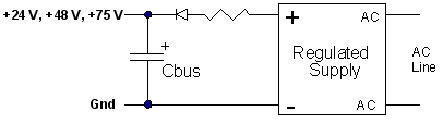
S200: Power Supply DesignDesignThis section has additional considerations for DC power supplies. Single Power Supply OperationA single power supply can be used to provide main or motor power, and control power for the DC power input. The voltage range of a single supply is 20 V to 90 V. NOTE: The drive can be damaged if the supply voltage exceeds 90 V, even briefly. The DC level plus transients plus regenerative pump up MUST NEVER exceed 90 V. Wire the single supply +terminal to J1-3 (+Bus) and to J1-1 (+CTRL) and the power supply –terminal to J1-2 (Bus/Ctrl Gnd). This power supply is typically unregulated, but a regulated supply can also be used. The power supply outputs must be isolated from the power line. See Regulatory Information for more details on isolation requirements. Wire both the power supply negative terminal and the drive chassis to earth for safety. The maximum continuous and peak (3 sec) main power and current at 75 V bus for the S200 DC drives is shown in the table below.
The next figures provide representative connection diagrams and some detailed recommendations.
WARNING: An appropriately-sized output capacitor in the main power supply is the key to economically delivering high peak power. In most applications, the capacitor supplies much of the peak power needed to accelerate the motor and inertia (under 20 ms). It also lowers the cost of the supply by reducing its silicon current. In addition, it also absorbs regenerated energy with a limited pump up of voltage and stabilizes the bus voltage for better dynamics. NOTE: While the maximum peak-to-continuous power capability ration is 3:1, most applications have much higher ratios. The requirement that the main supply have a high peak-to-continuous power ratio is very important in selecting or designing the power supply.
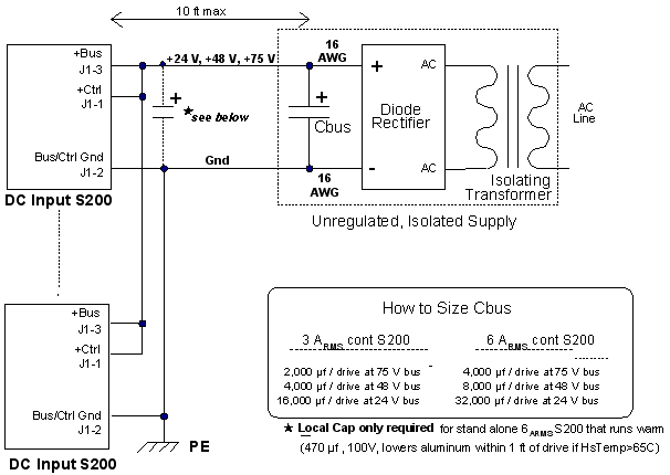
Main Supply Output Capacitance (J1-3 to J1-2)The location of the main output capacitor is not critical. Up to 10 ft from the drive is an acceptable length, as long as the wire is sized so resistive drops at peak current are low. Voltage clipping of the inverter can cause the peak bus current to equal the motor current. A good rule is to size the bus wiring for 18 ARMS x rt(2) = 25.4 ARMS peak per drive. Use at least 16 AWG. The inductance of the bus and ground wiring is not critical because the internal drive bus capacitance can handle all the PWM current in most cases. Servos put high peak power demands on the power supply. The easiest and best way to build a power supply to deliver and absorb pulses of peak power is for the supply to have an appropriately-sized output capacitor.
This can be the output capacitor of an unregulated power supply or a capacitor in parallel with the output of a regulated supply. In most cases, this capacitor does not need to be close to the drive, so a single capacitor can be shared by multiple drives. This capacitor does several jobs: Bus capacitance absorbs net regenerated mechanical energy from the inertia when the motor decelerates. NOTE: If the regenerated mechanical energy is high, additional bus capacitors can be added in parallel. The bus capacitance can be increased almost without limit. The over-voltage fault is a non-latching fault that turns off the inverter transistors when the bus voltage is above the over-voltage threshold. An over-voltage fault trip interrupts the regeneration of mechanical energy back to the bus. This limits the bus voltage rise and protects the drive. However, it interrupts motor torque, so the machine cycle is affected. In most cases it is undesirable to allow the bus voltage to pump up to the over-voltage fault threshold. In many applications, much or all of the rotational mechanical energy is dissipated as heat in the motor windings when the motor decelerates. The maximum regenerated rotation energy back to the bus occurs (counter-intuitively) during a low torque deceleration from high speed. In this case, the resistive losses in the motor are low. If mechanical drag is low, much of the stored rotational energy is regenerated to the bus. Bus capacitance absorbs net regenerated inductive energy from the motor winding when the drive is disabled or faulted. NOTE: Failure to provide adequate external capacitance on the main bus can damage the drive. The regeneration of motor inductive energy allows some pump up of the bus voltage above the bus over-voltage threshold. Bus capacitance improves motor dynamics by holding the bus voltage stable during acceleration. Bus capacitance lowers peak current requirements in the silicon of the power supply. In most cases, a bus capacitor does not need to be mounted close to the drive.
Bus capacitor for multiple drives NOTE: Bus capacitance can be tweaked experimentally. Increase bus capacitance if there are overvoltage trips. In general, there is sufficient bus capacitance if the bus voltage variation is ± 5 V (from 75 VDC) during the machine cycle. Check the bus voltage with an oscilloscope. Scope ground on J1-2 (Bus/Ctrl Gnd) and probe on J1-3 (+bus), Hor: 5 ms/div. NOTE: Some bus voltage variation is normal and required for the output bus capacitor to supply or absorb energy. Bus over-voltage fault (non-latching) Unregulated power supply Regulated power supply A low ohm (< 1 Ω) power resistor between the power supply and the capacitor may be desirable. By reducing the stiffness of the voltage across the capacitor, it enhances the ability of the capacitor to supply current to the drive during motor acceleration and prevents the current limit of the regulated supply from cutting in. The AC and DC bus currents also flow in the Control or Bus terminal. The size of the ground wire to the drive should be no smaller than the positive Bus wire. A larger wire size yields a cleaner ground. If a separate control supply is used, connect the control supply ground and main bus supply ground together at, or near the drives, but not at the supplies. NOTE: Be aware of bus resonance. Current can oscillate between capacitors in any distributed DC power system with the capacitor located apart and connected in parallel with wires. The capacitors and wiring inductance form an underdamped LC circuit that can ring when excited by PWM currents. This ringing is most easily seen by monitoring the current in the bus wiring of the drive with a current probe. The ringing occurs if the current probe shows a large (> 10 A) quasi-sinusoidal current in the 1 to 10 kHz range. While it is more difficult to see in voltage, it does cause a small sinusoidal voltage (few volts) to occur across the drive +Bus (J1-3) to Gnd (J1-2) terminals. Occasional bursts of bus ringing are usually not too serious, but sustained or too frequent ringing is undesirable because high currents can cause heating of wires and capacitors. The simplest way to squelch bus ringing is to lower or change the inductance of the bus wiring with the following:
Recommended External Bus Capacitors
Two Power Supply OperationPowering the drive control power separately from the bus power has the advantage that fault and status information is preserved when bus power is down for safety. Wire the control supply positive terminal to J1-1 (+CTRL) and the control supply negative terminal to J1-2 (Bus/Ctrl Gnd). Wire the main supply positive terminal to J1-3 and its negative terminal to J1-2. J1-2 is a shared ground for control power and main power. Separate ground wires from the two supplies should join at or near the shared drive ground pin (J1-2). NOTE: The drive can be damaged if the supply voltage exceeds 90 V, even briefly. Control Supply (J1-1 to J1-2)The voltage range of the control supply is +10 to +90 V. This supply can either be unregulated or regulated. However, it must be isolated from the power line as its negative terminal is typically earthed for safety and commoned with main power negative terminal. For reliable starting, the control supply should have a peak power rating of at least 20 watts. A typical continuous control power drawn by an S200 DC drive is 2 to 8 watts. A single, relatively low power, low voltage supply (+12 V or +24 V) can provide control power and I/O power for multiple drives.
Multi-Axis ConsiderationsIn multi-axis applications, the drive's power terminals can either be wired separately to the power supplies or paralleled locally (daisy-chained) and then wired to the power supplies. In the latter case, increase the wire size to handle the higher current. NOTE: Locally paralleling the main power terminals of multiple drives parallels the internal bus capacitors of the drives (200 µf per drive). This allows the PWM currents of the drives to spread out, thereby lowering the temperature of the capacitor in the hottest drive.
|
|||||||||||||||||||||||||||||||||||||||||||||||||||||||||||||||||
|
Inductance in AKM motors mated to S200s can be as high as 5 mH (line-to-line). The inductive energy stored in a 5 mH motor at 18 ARMS is calculated as:
E winding = 0.75 x Inductance line-to-line x IRMS x IRMS
= 0.75 x 0.005 henry x 18 RMS x 18 RMS
= 1.2 joules
The bus capacitor needed to absorb the regenerated energy (EREGEN) is sized using the general rule that the energy stored in the capacitor be a minimum of 5 * EREGEN. This limits the voltage increase on the bus due to regeneration to 10% of the DC value. Using this general rule to find the minimum bus capacitance for the motor in the above example (for simplicity, ignore that a fraction of regenerated inductive energy is dissipated in the motor):
E bus cap = 5 x 1.2 joules = 6 joules
E bus cap = 1/2 Cbus x DC voltage x DC voltage
Assuming that the bus DC voltage is 75 volts:
Cbus = 2 x Ebus cap/(75 V x 75 V)
= 2 x 6 joules/(75 V x 75 V)
= 2,133 µF
The internal S200 bus capacitance is 200 µf, which is less than 10% of the required capacitance for energy absorption.
The bus supply for a group of S200 drives must have enough total capacitance to handle brief, high-current bus transient flows (positive and negative) a few milliseconds without excessive bus voltage variation. The peak output power of a 6/18 ARMS DC S200 can be as high as 1.5 kW (1.5 kW = 18 ARMS x rt(2) x 60 V (emf + IR)). This is an energy flow of 3 joules for 2 ms or 15 joules for 10 ms.
Mechanical energy is estimated by considering the load to be pure inertia and measuring the velocity transition times. A full torque acceleration or deceleration of an inertia load yields a triangle power pulse with an energy (in joules) half of the peak power (in watts) multiplied by the velocity ramp time (in seconds) from zero speed. Motor acceleration can be monitored by mapping velocity and torque to DAC monitor pins (J4-14, 15) and looking at them with a scope. Set DM1Map to VelFB and DM2Map to IFB. See the I/O Setting tab in S200 Tools. At a peak power flow to the shaft of 1 kW = (25 A x 40 V EMF), the energy delivered vs acceleration time is:
5 ms 2.5 joules
10 ms 5.0 joules
15 ms 7.5 joules
The capacitor energy absorbed or delivered for a 5 V change from a 75 bias is:
3 joules for 8,000 µf
7 joules for 20,000 µf
16 joules for 45,000 µf
Bus input power can be estimated by adding motor shaft power and motor resistive winding loss. The shaft power equation is:
Shaft power (watt) = Torque (N-m) x Speed (rad/sec)
where, rad/sec = rpm/60 x 2π
The equation for motor resistive (heat) loss is:
Winding loss (watt) = 1.5 x Rline-to-line x IRMS x IRMS
| | | Copyright © 2001-2021 Motion Engineering |