
|
|
| . |
S200: J1
|
||||||||||||||||||||||||||||||||||||||||||||||||||||||||||||||||||
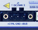 |
See Connector Locations. |
See DC Input Drive Wiring Diagram.
|
NOTE: Refer to the DC Power Supply Requirements section for detailed requirements selecting a compatible power supply.
Warnings
To avoid damage to the connector and drive, NEVER plug or unplug the J1 connector with power applied.
+CTRL
Control power input. The DC drive accepts +10 to +90 VDC on this input referenced to J1-2. An isolated regulated or isolated unregulated power supply can be used. This input can be connected to +Bus input (J1-3) and powered by the same supply as +Bus. The control power supply should be rated for 20 watts. While the power drain typically is 2 W to 8 W, a 20 W supply ensures reliable starting of the drive.
BUS/CTRL GND
Power return for the control and BUS power supplies. The BUS/CTRL GND is connected to I/O RTN internally in the drive.
+BUS
Main power input to the drive. The DC drive accepts +20 to +90 VDC on this input referenced to J1-2. An isolated regulated or isolated unregulated power supply can be used. The +Bus power drain with +Bus voltage at 75 VDC is in the range shown below. It varies according to the application and motor.
Signal |
S20330 (3 amp) |
S20630 (6 amp) |
| +Bus Continuous Power |
250 W |
500 W |
| +Bus Peak Power |
750 W |
1500 W |
PE Screw Connection
This chassis ground point must be connected to Protective Earth ground. The connection at the Protective Earth ground end must be hard wired (do not use a pluggable connection). A ground fault detector (RCD) cannot be depended on for safety.
Screw Terminal Connector
12 – 24 AWG Wire Range, Phoenix MSTB2,5/3-STF-5,08-BK
Spring Cage Clamp Connector
12 – 24 AWG Wire Range, Phoenix FKC 2,5/3-SFT-5,08-BK
Crimp Connector
Crimp Shell
14 – 20 AWG Wire Range, Phoenix MSTBC 2,5/3-STZF-5,08-BK
Crimp Contact
14 – 16 AWG Wire Range, Phoenix MSTBC-MT 1,5-2,5
Crimp Contact
18 – 20 AWG Wire Range, Phoenix MSTBC-MT 0,5-1,0
For more information, see www.phoenixcon.com.
Bus Voltage (J1-3 to J1-2) |
+20 VDC to +90 VDC |
Bus Supply Current |
48 VDC Bus |
75 VDC Bus |
| S20330 Continuous Peak (3 sec) |
3.3 Adc at 160 W 10 Adc at 480 W |
3.3 Adc at 250 W 10 Adc at 750 W |
| S20630 Continuous Peak (3 sec) |
6.7 Adc at 320 W 10 Adc at 960 W |
6.7 Adc at 500 W 20 Adc at 3000 W |
Bus Output Capacitance (min) |
48 VDC Bus |
75 VDC Bus |
| S20330 | 4000 µf, 63 V |
2000 µf, 100 V |
| S20630 | 8000 µf, 63 V |
4000 µf, 100 V |
| Bus Supply Characteristics | The BUS Supply should have the following characteristics:
Typical BUS Supply:
|
| Wiring from Bus Supply to Drive | 10 ft maximum 16 AWG (minimum) Twisted pair Daisy chaining of multiple drives is OK. No contactor or switching in the BUS wiring. |
| Control Voltage (J1-1 to J1-2) |
+10 VDC to +90 VDC |
| Control Supply Type | Isolating Unregulated or Regulated Common GND with bus supply and I/O RTN. 20 watt supply or 1 amp short circuit. |
| Control Supply Wiring | Wire control (J1-1) to Bus (J1-3) or Wire control (J1-1) to separate supply to preserve status and fault information. (+10 VDC to +30 VDC supply can be shared by Control and I/O) |
| Control Supply Current | 20 to 110 mA at 75 VDC 60 to 330 mA at 24 VDC 125 to 660 mA at 12 VDC |
Bus voltage outside the operating range (20 to 90 V) causes an undervoltage or overvoltage fault. Undervoltage and overvoltage faults self-clear when the fault condition clears.
NOTE: Do NOT allow the Bus Voltage to exceed +90 VDC as it can damage the drive.
Target design center voltage for unregulated supply is +70 to +75 VDC. This provides 15 to 20 VDC margin for line tolerance, transformer regulation, and regen pump up. Design center voltage for a regulated supply can be up to +80 VDC.
The control voltage range for normal operation is +10 VDC to +90 VDC. The control voltage can either be wired to the bus voltage so one supply can power the drive, or from a separate supply. Separately powering the control from the bus allows the bus to be powered down for safety while drive status and fault information remain available. A single +10 VDC to +30 VDC supply can be shared by Control and I/O.
NOTE: Do NOT allow the Control Voltage to exceed +90 VDC as it can damage the drive.
Provide safety isolation with the external bus and control supplies from the power line.
NOTE: The drive cannot be powered from an electrically hot supply as it does not contain an isolation barrier.
The Ctrl and Bus voltages and non-opto coupled I/O grounds (I/O RTN) are commoned inside the drive. The Ctrl and Bus power supplies share a ground pin (Bus/Ctrl Gnd). Join and connect to the negative terminals of the Ctrl and Bus power supplies. The I/O RTNs are normally connected to the signal ground of the system. (Some of the I/O is opto coupled and have separate returns. Be sure to thoroughly review this document for details.)
The power supply negative terminal should be grounded somewhere in the cabinet. The chassis should also be grounded. In normal operation there should be no significant voltage between ground and the Bus/Ctrl Gnd and I/O RTNs.
NOTE: The maximum voltage allowed between Bus/Ctrl Gnd and chassis is 100 VDC.
There is a minimum requirement on the output capacitance of the bus power supply for the S200 DC Input Drives. This capacitor is needed to absorb energy during motor deceleration and motor disable. It also helps provide energy during motor acceleration. For multiple S200 drives operated from one supply, the recommendation is to increase the capacitance according to the number of drives. For example, for four 6 A / 18 Arms DC S200 drives powered from one 75 VDC supply, the recommended minimum bus output capacitance of the supply is 4 x 4,000 µf = 16,000 µf. Bus capacitor voltage rating should be 100 V. Bus capacitor type is aluminum electrolytic.
Do NOT put E-Stop switches or contactors between the drive bus pin (J1-3) and the power supply bus capacitor. There is a risk of damage to the drive if the bus is disconnected from the power supply capacitor when the drive is enabled. The motor does not need to be rotating to regenerate energy. The motor windings store magnetic energy that regenerates back to the supply when the drive is disabled.
E-stop switches can safely be located in series with the primary winding of a step down transformer. If individual axis E-Stop switches are required, connect a local (unswitched) capacitor (1,000 µf, 100 V) across the drive bus terminals (J1-3 to J1-2). If the buses of individual drives are to be fused, select the fuse type and rating for high margin.
S20330 (3 amp) |
S20630 (6 amp) |
| 7 A, Slo-Blo (Bussmann MDA-7) | 15 A, Slo-Blo (Bussmann MDA-15) |
| | | Copyright © 2001-2021 Motion Engineering |
