S200: Regulatory Information
Conformance Requirements
The equipment described herein has been developed, produced, tested, and documented in accordance with the corresponding standards. During use conforming with requirements, the equipment is not dangerous for people or equipment. Use conforming with requirements means that the safety recommendations and warnings detailed in this documentation are complied with and that the applicable regulations for safety (machine directives, etc.) and noise suppression (EMC Directives) are observed while operating the drive. At the end of its lifetime, dispose of or recycle the drive according to the regulations applicable at that time.
CE Approval
The CE initials confirm that the S200 drives satisfy all requirements of CE Directives. However, the equipment is not ready to operate without additional installations (cable, motor, etc.). Thus, all necessary tests and measurements had to be made on a typical installation. The test installation with all peripheral devices, as well as the test results and measurements are recorded in detail in documentation that is available from the manufacturer on request.
CE EMC Compliance
If the connection method on your machine is different from the ones pictured in this documentation, or in the event of use of components other than those specified, adherence to CE interference limit values cannot be guaranteed.
The machine builder should incorporate good EMC installation and wiring practices in the machine design. Some machine designs require more EMC consideration than others. For example, a multi-axis machine generates more noise than a single-axis machine. Therefore, multi-axis machines may require additional noise reduction techniques, such as a metal enclosure or clamping of cables shields to an RF ground.
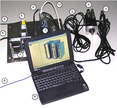
CE Test Setup
AC MODELS S2XX6X-VTS
| |
 |
| |
- S200 AC Drive: S20360-VTS
- Motor Feedback Cable: CF-DA0111N-05-0 (CF-DA0111N-50-0 for conducted emissions)
- Motor Power Cable: CP-102AAAN-05-0 (CP-102AAAN-50-0 for conducted emissions)
- Motor: Kollmorgen AKM43K-ANCNC-00
- Line Filter: MTE RF30006-4.
NOTE: Cable between filter and drives shielded with shield tied to PE with a 360 degree termination at each end of the cable.
- Cords for AC Mains Connection
- 5V Power Supply for Enable Opto
- Personal Computer
- Serial Cable (for setup and diagnostics)
- Shielded I/O cable with DSUB Shell grounded at each end.
|
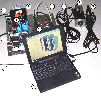
(DC MODELS S2XX3X-VTS)
| |
 |
| |
- S200 AC Drive: S20630-VTS
- Motor Feedback Cable: CF-DA0111N-05-0 (CF-DA0111N-50-0 for conducted emissions)
- Motor Power Cable: CP-102AAAN-05-0 (CP-102AAAN-50-0 for conducted emissions)
- Motor: Kollmorgen AKM43K-ANCNC-00
- Safety isolated DC
- Cords for AC Mains Connection
- 5V Power Supply for Enable Opto
- Personal Computer
- Serial Cable (for setup and diagnostics)
- Shielded I/O cable with DSUB Shell grounded at each end.
|
Declaration of Conformity
In our Declaration of Conformity, we affirm our compliance with Directive 73/23/EEC (Low voltage Directive) and with Directive 89/336/EEC (EMC Directive).
EMC testing was done according to EN61800-3:1997 with the incorporation of amendment A11:2000 (Emission limits according to chapter 6.3.1 of that regulation, First environment / restricted distribution) for the following drives:
| |
- S20260-VTS, S20360-VTS, S20330-VTS,
S20630-VTS, S20260-SRS,
S20360-SRS,
S20330-SRS, S20630-SRS, S20260-SDS,
S20360-SDS,
S20330-SDS, S20630-SDS
- Currently undergoing conformity testing:
S20660-VTS, S20660-SRS, S20660-SDS
|
During assembly of our product in a machine, startup (that is, normal operation) is prohibited until the end-product complies with Directive 89/392/EEC (Machine Directive) and directive 89/336/EEC (EMC Directive).
The machine manufacturer must prove that the complete system conforms with all relevant European Directives.
Drive conformance to specified standards is certified by the Declaration of Conformity in this documentation. See the CE Declaration of Conformity Certificate.
Installation and Commissioning
Installation and wiring of the drive must be completed only by qualified personnel having a basic knowledge of electronics, installation of electronic and mechanical components, and all applicable wiring regulations.
Only qualified personnel having broad knowledge of electronics and motion control technology are to commission the machine utilizing the drives.
This documentation should be read in its entirety. This appendix contains important regulatory information not necessarily covered in earlier chapters. The material in this section should be taken into consideration to ensure compliance with applicable regulatory requirements. This section alone does not contain all the information needed to install and operate an S200 drive. General information on installation and wiring are explained in detail in previous sections.
Safety Requirements
As the user or person applying this unit, you are responsible for determining the suitability of this product for the application. In no event will Kollmorgen be responsible or liable for indirect or consequential damage resulting from the misuse of this product.
Read this documentation completely to effectively and safely operate the S200.
European Compliance
In Germany, these include:
| |
- DIN VDE 0100
Instructions for setting up power installations with rated voltages below 1000 V).
- DIN - EN 60204 - Part 1, (VDE 0113, part 1)
Instructions relative to electric equipment in machines for industrial use.
- DIN EN 50178, (VDE 0160)
Instructions relative to electronic equipment for use in power installations.
|
Low Voltage Directive and EN50178
To ensure compliance with the Low Voltage Directive and EN50178, following these requirements:
| |
- Electronic drives contain electrostatic sensitive devices, that can be damaged when handled improperly. Qualified personnel must follow ESD protection measures. For example: wear grounded heel and wrist straps when contacting drive.
- The climatic conditions shall be in accordance with EN 50178 climatic class: Type B, temperature and relative humidity: Class 3K3.
- The drives shall be installed in an environment of Pollution Degree 2 or better.
- The S200 drives are not considered portable and are to be mounted in the intended manner in a motor/control cabinet having adequate strength and thickness with acceptable spacing for the end product classification accessible by qualified personnel only. The enclosure/cabinet shall meet at least the requirements of Protective Type IP2X according to 5.1 of EN 60529. If the top surface of the enclosure/cabinet is easily accessible it shall meet at least the requirements of the Protective Type IP4X.
- Care shall be taken to ensure that the larger device or enclosure that accommodates the built-in device provides protection against direct contact.
- The S200 drives may be erected in closed electrical operating areas if a protection against direct contact is available or assigned for by means of obstacles and/or a distance according to IEC 364-4-412.3 and IEC 364-4-412.4.
- Follow IEC 536-2 and IEC 1140 for installation protection against electric shock.
- Installation shall be performed in accordance with local electric codes, local accident prevention rules, EN 50178 and EN 61800-3.
- Never connect or disconnect any drive connectors or terminals while the power is switched on.
- Due to high leakage current, permanently install this drive (hard wired or fixed type). The PE connection shall be made by two separate protective conductors satisfying the requirements for protective conductors as given in 543 of HD 384.5.54 S1 between the earth ground and the PE terminal(s) on the drive, or by a protective conductor having a cross section of at least 10 mm2 Cu. The S200 drives are designed to Protective Class I.
- The discharge time for the bus capacitors may be as long as 5 minutes. After disconnecting the drive from the ac mains be sure to wait 5 minutes before removing the drive’s cover and exposing live parts.
- The finished installation shall comply with the requirements of the IEC 364-4-41 series of standards.
- The cables and leads (except the protective conductors) used in the erection of the S200 in an installation which are accessible for contact without opening or removing a barrier or are laid on extraneous conductive parts shall have double or reinforced insulation between the core and the surface or shall be surrounded by a metal screen having a satisfactory current-carrying capacity in the event of a short-circuit between the core and the screen.
- When installing the S200 into its operating location, it shall be ensured that any existing protective separation according to 5.2.18 of EN50178 is maintained throughout the entire length of the circuit in question. In installations the compliance for of the measures for protective separation shall be checked by visual inspection.
- Refer to Sections 1 and 4 of this documentation for external fusing information.
- Motor cable shield must be connected to protective earth.
- During periods of extreme regeneration or excessively high input voltage the temperature of the regen resistor may exceed 70 °C.
- When using an external regen resistor, if regen cabling is accessible during normal machine operation, regen resistor cable should be rated at 450 VDC and shielded with shield connected to PE.
- Consult the factory before using this product on a circuit protected by a residual-current-operated protective device (RCD).
- All covers shall be closed during operation.
- The S200 drives should be used within their specified ratings.
|
UL and cUL Conformance
The S200 drives are UL and cUL Recognized to UL 508C under UL File number E137798. Consider the following points to ensure that final installation meets UL requirements:
| |
- The drive should be used within its specified ratings.
- The drive should be mounted in the intended manner in an enclosure having adequate strength and thickness with acceptable spacing for the end product classification.
- The spacing from the exposed live-metal parts to the enclosure wall should be in accordance with the requirements for the overall equipment.
- These drives shall be used in a pollution degree 2 environment in order to comply with the spacing requirements of UL 840 and UL 508C.
- The UL temperature tests were done with a metal heat plate with overall dimensions, 6 in x 12 in x 1/8 in. The machine builder is responsible for ensuring adequate heat sinking capability in the final installation.
- The thermal protective device(s) provided integral to the motor drives were not evaluated by UL.
- The terminals are suitable for factory wiring only.
- These motor drives have not been evaluated to provide solid-state overload or over speed protection.
- The DC models were evaluated by UL for use with an isolated power supply rated no more than 150 V open circuit secondary voltage and 10 kVA secondary power. This combination shall be maintained to satisfy UL requirements.
|
Additional Safety Precautions
Motor Case Grounding
Insure that the motor’s case is connected to PE ground. The fourth wire in the motor cable connecting J2-1 to the motor case accomplishes this.
WARNING
If the motor is not properly grounded, dangerous voltages can be present on the motor case due to capacitive coupling between the motor windings and case.
Requirements for Safe Operation of the Drive
It is the machine builder’s responsibility to insure that the complete machine complies with the Machine Directive (EN60204).
The following requirements relate directly to the servo controller:
Emergency Stop
WARNING
If personal injury can result from motor motion, the user must provide an external hardwired emergency stop circuit outside the drive. This circuit must simultaneously remove power from the drive’s motor power terminal J2-2, J2-3, and J2-4 and disable the drive (by open circuiting the connection to J4-2).
NOTE: The motor will coast under this condition with no braking torque.
WARNING
If braking torque is required to quickly stop the motor, a dynamic brake can be added that loads the motor’s windings resistively. The motor should not be loaded until the servo drive is disabled. The holding brake, optional on Kollmorgen motors, is not intended to stop a spinning motor. It is designed to prevent a stopped motor from rotating due to an applied torque.
Avoid Unexpected Motion
WARNING
Always remove power from J1 and wait 5 minutes before working on the machine or working anywhere where injury can occur due to machine motion.
Avoid Electrical Shock
WARNING
Never power the servo drive with the cover removed or with anything attached to circuitry inside the cover.
If the drive must be removed from the cabinet, wait at least five minutes after turning off power before removing any cables from the drive or removing the drive from the mounting panel.
Never connect or disconnect any wiring to the drive while power is applied. Always power down and wait five minutes before connecting or disconnecting any wires to the terminals.
Avoid Burns
WARNING
The temperature of the drive’s heat sink and housing as well as an external regen resistor may exceed 60° C. Therefore, there is a danger of severe burns if these regions are touched.
Prevent Damage to the Drive
Follow these guidelines to prevent damage to the servo drive during operation:
| |
- Never plug or unplug connectors with power applied.
- Never connect or disconnect any wires to terminals with power applied.
- If the drive indicates a fault condition, find the cause of the fault and fix it prior to resetting the fault or power-cycling the drive.
|
EMC Compliance with EN61800-3
Use in a Domestic Environment
WARNING
The products covered in this documentation are of the restricted sales distribution class according to IEC 61800-3. In a domestic environment this product may cause radio interference in which case the user may be required to take adequate measures.
Because applications differ, it is impossible for the drive manufacturer to guarantee machine EMC compliance. In some applications, it may be necessary for the machine builder to incorporate more EMC mitigation techniques than Kollmorgen had to use in the EMC test setups.
General Suggestions to Improve Machine EMC Performance
| |
- Use Kollmorgen cables – Kollmorgen cables have been designed with EMC considerations in mind. Because subtle differences in cable construction can cause dramatic changes in EMC performance use of Kollmorgen's Kollmorgen motor power and feedback cables is recommended.
- When joining or splicing sections of cable, be sure to maintain the integrity of the cable shield along the entire length of the finished cable.
- Separate cables according to type - AC Mains input, motor power and signal cables should be separated from each other by at least 100 mm (4 in) to avoid cross coupling between them. If cables of different types have to cross, they should do so at a 90° angle.
- Route wiring close to machine frame - It is a good practice to run wires along the machine frame (local ground) whenever practical, this couples some high frequency noise/signals that could otherwise be troublesome directly to the local ground.
- Remove paint from all drive, filter, and cable clamp mounting locations.
- Add clamp-on ferrites to cables – Adding clamp-on ferrites to noisy cables can reduce emissions by absorbing RF energy before it is radiated.
- Use the appropriate line filter – A line filter is required for CE applications, more information on line filter selection can be found in D.10
- Add a balun to the motor power cable – adding a balun in series with the U, V and W phases of the motor power cable can attenuate both conducted and radiated emissions.
- Ensure that cables shields have a good RF ground – more information on this can be found in D.10.
|
AC Mains Conducted Emissions
Line Filter
To meet the CE-conducted EMC requirements, an external line filter (in series with the AC mains) is necessary. It is the responsibility of the machine builder to choose filter(s) appropriate for the application. Kollmorgen is willing to assist in this choice. Often, the decision is made to filter the machine as a whole instead of filtering the individual drives.
Mount the line filter as close as possible to the point where incoming power enters the machine/cabinet. Locate the drive(s) as close as possible to the line filter. To provide maximum high frequency filtering, remove any paint from between the filter, the drive and the conductive surface, ground plane to which they are bonded. For maximum benefit, separate input wiring to the line filter and output wiring from the line filter from each other.
During CE testing, three (3) line filters were qualified for use with 50 m motor and feedback cables to represent worse-case, conducted emissions compliance. The following filters were used:
Corcom 6EQ1 (single phase)
Corcom 36FCD10 (three phase)
MTE RF30006-4 (three phase)
Information on these and other filters can be found at:
Corcom, Inc.
USA 1-800-468-2023 or 847-680-7400
Germany 49-89-857920
http://www.cor.com
MTE Corporation
USA 1-800-455-4MTE
International 1-262-253-8200
http://www.mtecorp.com
NOTE:
For complete instructions on wiring an AC version S200 drive refer to the AC Input Wiring Diagram. For complete instructions on wiring a DC version S200 drive refer to DC Input Wiring Diagram.
Motor Power Cable Filtering
In typical applications, the S200 drives do not require additional filtering in the motor leads. Machines with many drives and long motor power cables may require an external balun in series with the power motor power cable to reduce the machine’s conducted emissions. Additional information can be found in Pacific Scientific Application Notes 106 (Reducing Motor Drive Line Noise) and 107 (Reducing Motor Drive Radiated Emissions).
NOTE: Balun PN: 104-090003-01
Ground Cable Shields
The Motor Power (J2), Feedback (J3), Command I/O (J4), and Serial Port (J5) cables must be shielded and the shields should be connected to PE. The safety PE connection can be made through connector pin or shell.
| Current Rating |
60 A sinewave pk (42 ARMS) 5 sec |
| Inductance |
340 µh nominal |
| Energy Rating |
7200 µJ nominal |
| Resistance |
0.021 Ω nominal |
| Gap |
10 mil |
WARNING
All cables used with the S200 drives should be shielded with the shields connected to PE. Dangerous voltages, resulting from cable capacitance, exist on some cable shields if the shields are not connected to PE ground.
Avoid Crosstalk
EMC testing was performed using a single drive with standard wiring. When a machine incorporates several drives or is designed for use in an environment requiring very low emissions, additional steps may be necessary to reduce the overall machine emissions and/or susceptibility. High frequency grounding of cable shields may help reduce radiated and conducted emissions as well as protect against susceptibility to external and self-generated noise.
WARNING
To avoid the risk of crosstalk, keep the motor and feedback cables away from sensitive signal cables (i.e., telephone and intercommunication lines). Shield all cables used with the S200 drives with the shields connected to PE.
High Frequency Grounding of Cable Shields
When a cable with a separate inner foil shield and outer braided shield is used, EMC performance may be improved by connecting the foil shield to the PE location on the connector and removing about 10 mm (0.5 in) of the outer cable jacket close to the drive [within 0.6 m (2 ft) of the drive] to expose the braided shield and clamping the outer braided shield to the ground plane with a 360°-type clamp.
If a ground plane is available at the motor end of these cables, similar use of a conductive clamp at that end to connect the shield to the ground plane may help as well. Clamping the cable shields to PE typically reduces the level of emissions and increases the level of immunity to interference.
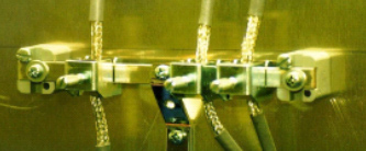
Example of 360° clamping of cable shields
Regen Resistor
Regen Wiring (AC drives)
For complete instructions pertaining to an external regen resistor with an AC input drive, refer to the AC Input Drive Wiring Diagram. In addition to the information in that section, users installing drives for use in a CE installation should use an appropriately-grounded, shielded regen cable to reduce overall system emissions.
Accessible Regen Cables
WARNING
When using an external regen resistor, if regen cabling is accessible during normal machine operation, the cable should be a shielded cable rated at 450 VDC with the shield connected to PE.
High Frequency Grounding of Regen Cable Shield
When using a regen resistor in a CE installation, the cable should be appropriately rated and have a braided shield connected to PE for safety, and clamped to the ground plane with a 360° clamp for EMC purposes.
Additional EMC Information Sources
Additional information on EMC performance and noise reduction techniques can be found on the Kollmorgen website (http://www.DanaherMotion.com):
Kollmorgen Application Note EMI Noise Checklist
Pacific Scientific Application Note 106 - Reducing Motor Drive Line Noise
Pacific Scientific Application Note 107 - Reducing Motor Drive Radiated Emissions
Customer Support
Kollmorgen products are available world-wide through an extensive authorized distributor network. These distributors offer literature, technical assistance, and a wide range of models off the shelf for the fastest possible delivery.
Kollmorgen sales engineers are conveniently located to provide prompt attention to customer needs. Call the nearest office for ordering and application information and assistance or for the address of the closest authorized distributor. If you do not know who your sales representative is, contact us at:
Kollmorgen
203A West Rock Road
Radford, VA 24141 USA
Phone: 1-540-633-3400
Fax: 1-540-639-4162
Email: customer.support@danahermotion.com
Website: http://www.DanaherMotion.com
Previous | Back to Main Menu
|

