
|
|
| . |
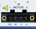
S200: J2
|
|||||||||||||||||||||||||||
 AC Drive |
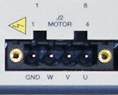 DC Drive |
See Connector Locations. |
|
|
PE Motor Case Ground
On S200 AC Input Drives, this point is connected to Chassis Ground.
On S200 DC Input Drives this point is connected to BUS/CTRL GND.
In either case this termination provides a convenient point for the motor ground connection and motor power wire shield. Local electrical code may require using the Earth Ground Chassis stud for this function.
Motor Phases: PHASE W,
PHASE V,
PHASE U
These three terminals provide the 3-phase power output to the motor.
NOTE: Observe motor polarity, connect phase U on the drive to phase U on the motor, etc. For nonstandard motor drive combinations, consult the factory for proper phase orientation.
Screw Terminal Connector
12 – 24 AWG Wire Range, Phoenix MSTB2,5/4-STF-5,08-BK
Spring Cage Clamp Connector
12 – 24 AWG Wire Range, Phoenix FKC 2,5/4-SFT-5,08-BK
Crimp Connector
Crimp Shell
14 – 20 AWG Wire Range, Phoenix MSTBC 2,5/4-STZF-5,08-BK
Crimp Contact
14 – 16 AWG Wire Range, Phoenix MSTBC-MT 1,5-2,5
Crimp Contact
18 – 20 AWG Wire Range, Phoenix MSTBC-MT 0,5-1,0
For more information, see www.phoenixcon.com.
| | | Copyright © 2001-2021 Motion Engineering |
