Creating a Simulated Network
Simulating a network can be done one of two ways, by capturing a dump file (snapshot) using the VM3 utility or manually creating a simulated network using the provided SimNetwork.txt file. A default meimem.sim file is also provided in the Win32 directory and is required to run Simulation Server.
Note: Although the default meimem.sim file may not match the simulated network you are trying to create, use the SimNetwork.txt to override the network and reallocate the associated objects.
Follow the procedures below to create a simulated network using the SimNetwork.txt file or to specify a different simulation file you created based on a real system.
Creating a Snapshot of an Actual Motion Network (Hardware Required)
Follow the procedure below to create a VM3 dump file (snapshot) of an actual motion network to use with Simulation Server. For more information about VM3, see VM3 Utility.
Note: If you create a snapshot of an actual physical hardware network, the SimNetwork.txt file is not required.
- Open a command prompt and run the Version Utility to verify your current physical network.
- Review the version.exe output to confirm all the nodes you want to simulate are present.
- Run VM3 and press CTRL+ F8 to create the meimem.sim file in the local directory.
- Verify the meimem.sim was created and run server.exe with the -simulate option to simulate the captured physical network.
Note: For more information about simulating the captured physical network, see Specifying a .sim File for Simulation.
Creating a Simulated Network Manually (No Hardware)
Simulation Server allows you to create a simulated network by modifying the provided SimNetwork.txt file. The SimNetwork.txt file is useful if you are unable to create a snapshot (dump file) of the system you want to simulate.
Use the SimNetwork.txt file to specify values that simulate nodes in a SynqNet network. Additionally, use the SimMotor.txt file to define the simulated motor behavior. For more information, see Defining Motor Simulated Behavior.
IMPORTANT!! The number of motors in the SimMotor.txt file must equal the motor count in the SimNetwork.txt file. Note some nodes may support more than one motor.
Using the SimReference.txt File to Build a Custom SimNetwork.txt
The easiest method of creating a simulated network manually is to use the provided SimReference.txt file to build a custom SimNetwork.txt file.
- Locate and open SimNetwork.txt and SimReference.txt files in the Win32 directory (default).
- From the SimReference.txt file, seach for the Nodes in the list and cut-and-paste the blocks into a custom simNetwork.txt or equivalent file to build your target network.
Note: Many devices have Options based on manufacturing configuration and features. If you are unsure which Option to use, contact the Node Manufacturer for details.
- Rename and Save and the file. However, make sure you specify the correct file name from the Command Line when running the simulator. For more information, see Running Simulation Server.
The SimNetwork.txt file is now properly configured. Proceed to the next step for defining motor simulation behavior.
Using the FPGA Identification Table to Build a Custom SimNetwork.txt
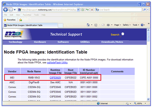
You cana lso use the FPGA Identification table to build your custom SimNetowrk.txt file. To find the node information in the FPGA table:
- Using your internet browser, access the Node FPGA Identification Table (http://support.motioneng.com/Hardware/Drives/FPGA/fpga_id_tbl.htm) and identify the vendor and name of the node to be simulated.
Note: For this example, the MEI RMB-10V2 node is used.

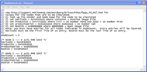
- In the SimNetwork.txt file set the Device ID, Product ID, Product Option and Boot ID. The following example is provided as a guide:

-
Set Device ID
to: 0xXXXXXXXX where XXXXXXXX = Runtime Image File.
Example, XXXXXXXX = 0xCOFE0029.
- Set Product ID to: 0xYYYYZZZZ where YYYY = Vendor ID Number and ZZZZ = ID Product Number.
Example: YYYY = COFE and ZZZZ = A001 and is written as 0xCOFEA001
- Set Product Option to: 0xAAAAAAAA where AAAAAAAA = ID Product Option
Example: AAAAAAAA = 0000 and is written as 0x00000000
- Set Boot ID to: 0xBBBBBBBB where BBBBBBBB = Boot Image File.
Example: BBBBBBBB = C0FEB022 and and is written as 0xCOF0B022
Note: You can add additional nodes by copying the node information for as many nodes as you require. However, verify the Node Count is properly set to the correct number of nodes you have specified.
- Click File, Save.
Note: You can rename the file. However, make sure you specify the correct file name from the Command Line when running the simulator. For more information, see Running Simulation Server.
The SimNetwork.txt file is now properly configured. Proceed to the next step for defining motor simulation behavior.
Note: A simulation file is required to run simulation. If a simulation file can not be created, use the default meimem.sim that is included in the Win32 directory with your modified SimNetwork.txt file.
Previous | Next
|
