|
|
| . |
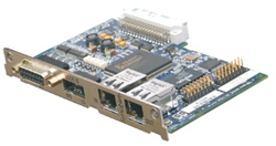
SynqNet Expansion Card
|
|||||||||||||||||||||||||||||||||||||||||||||||||||||||||||||||||||||||||||||||||||
|
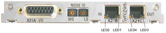
With these hexadecimal switches you can set the main and low significant bytes of the
Node ID seperately. SynqNet does not require an address for correct operation in the network,
however in some machines this can be a convenient way of identifying build options
to the application program.
LED# |
Name |
Function |
LED1 |
LINK_IN |
ON = receive valid (IN port) OFF= not valid, power off, or reset. See Also: LINK LEDs find Cable Problems |
LED2 |
CYCLIC |
ON = network cyclic BLINK = network not cyclic OFF = power off, or reset |
LED3 |
LINK_OUT |
ON = receive valid (OUT port) OFF = not valid, power off, or reset See Also: LINK LEDs find Cable Problems |
LED4 |
REPEATER |
ON = repeater on, network cyclic BLINK = repeater on, network not cyclic OFF = repeater off, power off, or reset |
Connection to the SynqNet network via RJ-45 connectors (IN and OUT ports) with integrated
LEDs.
Inputs (In): 24V (20...28V), opto-isolated, one high-speed input (Pin 4)
Outputs (Out): 24V, opto-isolated, Darlington driver
Pin |
Type |
Signal |
Description |
1 |
In |
+24V |
Power Supply |
2 |
Out |
NODEALARM |
Indicates a problem with the node |
3 |
Out |
OUT_01 |
Digital Output |
4 |
In |
IN_00 (fast) |
Capture Input (fast) |
5 |
In |
IN_04 |
Digital Input |
6 |
In |
IN_01 |
Digital Input |
7 |
In |
HOME |
Reference Switch |
8 |
In |
POSLIM |
Limit Switch (positive direction) |
9 |
In |
GND |
Power Supply |
10 |
Out |
OUT_00 |
Digital Output |
11 |
Out |
OUT_02 |
Digital Output |
12 |
In |
IN_02 |
Digital Input |
13 |
In |
IN_03 |
Digital Input |
14 |
In |
NEGLIM |
Limit Switch (negaitive direction) |
15 |
In |
NODEDISABLE |
Disables Node |
WARNING!
With SERVOSTAR 6xx terminals AGND and DGND (connector X3) must be joined
together !
| | | Copyright © 2001-2021 Motion Engineering |