|
|
| . |
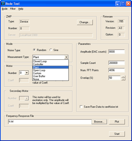
AutotuningOverviewAutotuning is a new feature to the Bode Tool. It is meant to tune simple systems quickly and with minimal user effort. The Autotuner is not intended to tune complex systems with many resonances, nor should it's results be accepted without someone looking them over as a sanity check. No Autotuner can succesfully tune every system. The Bode Tool's autotuner is optimized for tuning permanent magnet motors with current mode drives. Note: Make sure you have all appropriate error actions enabled when trying an autotuning out for the first time. How to use the AutotunerUsing the Autotuner1. Set up a plant FFT measurementThe Autotuner only operates off of plant measurements. Make sure you set the noise type to Random and set the measurement type to Plant.
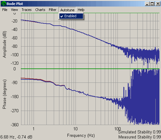
2. Make a measurementSet appropriate FFT measurement parameters as described in Running an FFT Measurement. 3. Verify that Autotune is enabledOnce the Bode Plot is displayed, check if the Enabled option is checked under the Autotune menu.
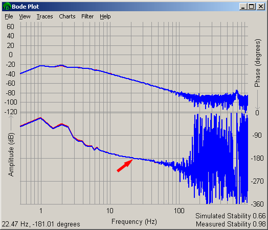
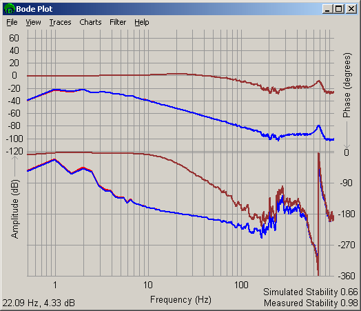
4. Determine the -180 degree pointThe Autotuner takes most of the guesswork out of tuning. It does require you to find a reference point for it, as a saftey precaution. Find the point where the open loop phase crosses through the -180 degree point (bottom blue trace). The red arrow shows this point for the example below.
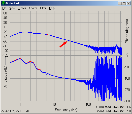
Tip:There may be several points where the open loop phase crosses through -180 degrees. Pick the first crossing that looks to not be a noise artifact. It may help to turn on smoothing ( Traces->Smooth Data) and set to to several percent to help see the crossover point smoothly. It is OK to pick the crossover point while the data is smoothed. 4. Find the corresponding open loop amplitude pointFind the open loop amplitude (top blue trace) point at the same frequency as found in step 3. Right click on this point. The red trace shows this point for the example below.
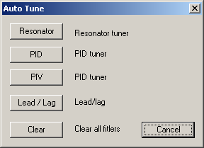
Tip:To find the open loop amplitude from the open loop phase, just move straight up from the point you found on the phase plot to the amplitude plot. 5. Turn off you amplifierYou will want to review the Autotuner's decision before turning on your amplifiers, in case you do not agree with the choice the Autotuner made. 6. Choose an Autotuning methodThere are four autotuning methods available. You must choose one by clicking on the appropriate button. You can also Clear out tuning parameters or Cancel. Clearing out tuning parameters will set PID and post filter settings to 0. You would not use this setting for motion. Canceling will exit the Auto Tune window without making any changes to the filter.
Tips:The different Autotuning methods have different characteristics: Resonator - This method is good for systems that are prone to "growling". It is a medium stability tuner. It tunes using a combination of PID and post filter methods. PID - This method is good for well behaved system. It can result in a system that "growls" if the encoders are of coarse resolution. It is a high stability tuner. This method uses only PID tuning parameters. PIV - This method is similar to the PID method, but has reduced "growling". It is a medium - high stability tuner. This method uses only PIV tuning parameters. Lead / Lag - This method is a good comprimise method. It is good at minimizing "growling" while being a high stability tuner. This method uses both PID and post filter methods. You can re-autotune your system with a different method if you want. Just repeat the above steps above starting at step 3. 7. Verify your tuningThe Autotuner will always return a set of tuning parameters. It is up to you to make sure they are stable for your system. The easiest way to verify this is to turn on the closed loop simulation and make sure that the frequency response is reasonable. You are looking for a peak in the simulated closed loop response (dark red / brown) of more thatn +6 dB or so. An example is shown below that show acceptable Autotuning with the Lead / Lag method (3% smoothing used to make the results easier to see).
Previous | Back to Table of Contents |
|||||||||||
| | | Copyright © 2001-2009 Motion Engineering |