|
|
| . |
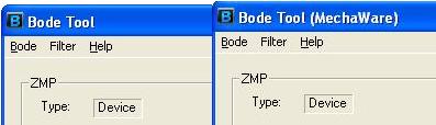
Filter Tool - Standard FirmwareOverviewThe Filter Tool window allows the user to modify the Filter Tuning parameters and immediately view changes in filter simulation plots. The Filter Tool is displayed as a separate window that is accessed while using any feature of the Bode Tool. This section describes how to view and change filter parameters for Standard Firmware, including PID, PIV, and all Post Filters. Note: As shown below, if the Bode Tool window indicates Bode Tool, this is for Standard Firmware. If the Bode Tool window indicates Bode Tool (MechaWare), this is for MechaWare Firmware. For more information about viewing and changing filter parameters for MechaWare Firmware, see Filter Tool - MechaWare FirmWare.
How to use the Filter ToolOpening the Filter ToolThe Filter Tool is opened from the main Bode Tool menu or from the Bode Plot menu by selecting Filter -> Filter Tool.
Simple Motor SetupThe setup tab in the filter tool allows simple configuration and management of the motor under test. It can do simple things, such as turning on the servos needed when testing. Without the setup tab, separate programs are needed to do these functions. Current Motion Number – This value indicates the MPI Motion Supervisor number used to abort motion and monitor motion state. This value always matches the current primary motor number selected on the main Bode dialog. Current Motor Number – This value indicates the MPI Motor and Filter number used to modify amp, error, algorithm, and filter coefficients (via PID/PIV/Algorithm/Post Filter tabs). This value always matches the current primary motor number selected on the main Bode dialog. Axis State - Shows the state of the motor as would be seen in Motion Console. This is commonly used to see that the motor is in an error state or idle state. Clear Fault - Click this button to attempt clear an axis state. Amp Enable - Shows whether the motor is enabled or not. Click the check box to toggle the amp enable status. Error Limit - Sets the error limit trigger. This is the maximum counts of following error that are allowed before the error limit action is taken. Error Action - The action taken when the Error Limit is triggered. Control Algorithm - This is the control algorithm type (PID, PIV, etc.) Polling Mode - If this is checked, the Setup tab is continually checking the status of all the values on the Setup tab. If an error is returned from the controller or communication with the controller is broken, this box becomes unchecked and the values are no longer updated. You can recheck this box if you remove the cause of the problem.
Accessing the Different Coefficient GroupsThe Filter Tool is primarily used to view and edit PID, PIV, and biquad post filter coefficients. Depending on the current filter algorithm, either the PID or the PIV tab is automatically displayed.
Viewing and Editing CoefficientsThe Filter Tool does not constantly poll the controller to determine if any coefficients have changed. If you change any filter coefficients in another program, click the Refresh button to make the Filter Tool read the latest coefficients. Coefficients changed in the Filter Tool will not take effect until the Apply button is clicked. When either the Apply or Refresh buttons are clicked, the Bode Plot window updates it's simulation The coefficients are always written to and read from the filter number specified in the First Motor Number on the main Bode Tool page. An example for standard firmware is show below where the First Motor Number is 0.
Viewing and Editing PID CoefficientsThe Filter Tool makes it easy to read and write PID coefficients to the controller. The Bode Plot window always updates its simulated traces to reflect the current filter coefficients loaded into the controller firmware.
To ensure the most current PID parameters from the controller, click the Refresh button on the Filter Tool. When you click the Refresh button, the Filter Tool retrieves the current filter coefficients from the controller. If the coefficients have changed since the Filter Tool last read them, the coefficients are updated on the screen. To change the current PID coefficients on the controller, edit one of the coefficients in the PID tab of the Filter Tool. When you are done making your changes, click the Apply button to load your changed filter coefficients to the controller. The coefficients are not changed on the controller until you click the Apply button. If the coefficients have changed since the Filter Tool last read them, the coefficients are updated on the screen. Viewing and Editing Biquad Post Filter ElementsThe Filter Tool is an easy way to view and edit biquad post filter elements on the controller. Select the Post Filter tab in the filter tool. IMPORTANT! biquad block sections cannot by added or removed by the filter tool. Instead, disable sections by setting their type to Unity Gain.
To ensure the most current biquad post filter information from the controller, click the Refresh button. The active post filter sections are displayed on the left by their Type name, in the order they are applied (top to bottom – top being section 0 applied first). To add an additional section, highlight the item labeled Click to Add Section. New sections start out as inert Unity Gains. To remove a section, click the Remove button while the section is highlighted. WARNING! Changing a section’s type to Zero Gain will remove the filter and all subsequent sections upon applying the changes. Caution, do not to disable a higher section if there are lower sections loaded or all lower sections will be disabled. To edit a section’s type or coefficients, select it from the list and proceed to make your edits on the right and click Apply. Updated plots are displayed in the Bode Plot window. Background on Biquad Post FiltersBiquad post filters can be intimidating to the uninitiated. This section covers how to specify the post filter elements you want in the Filter Tool and is not intended to cover what each filter type is and what it does. For more information, see MPIFilterPostFilterSection. There are six cascaded biquads for each filter object in the standard XMP and ZMP firmware. Each cascaded biquad is called a section and is specified by number (0-5). The biquad sections always start at number 0 and increment until all used sections are specified. All sections are specified in a continuous order (i.e. you can not have section 3 if you do not have section 2) If you not using biquad post filters, you do not need to specify any sections. In the Filter Tool, you navigate through your filter's biquad post filter sections by section number. Any Section Type can be assigned to any Section Number. The Section Type specifies the general behavior of the biquad post filter element. Currently there are nine Section Types (Unity, Single Order, Low Pass, High Pass, Notch, Resonator, Lead/Lag, None, and Digital Biquad). You can use any Section Type for any Section Number. The five edit boxes below the Section Number and Section Type are for specifying the specific filter parameters. Two example are shown below. The Low Pass filter only has one parameter, Corner Frequency in Hertz. The other four edit boxes are grayed out because they are not used in this type of filter.
The Resonator filter has three parameters, Center Frequency in Hertz, Bandwidth in Hertz, and Gain in dB. Gains in the biquad post filters are specified in dB. Frequencies are specified in Hz.
Measured Filter TabThe Measured Filter tab shows the tuning parameters used at the time the currently specified Frequency Response file's measurement was taken. If desired, you can press the Load to Controller button to load these parameters to the controller again. There are a few common uses for this tab:
|
|||||||||||
| | | Copyright © 2001-2009 Motion Engineering |