Pulse Configuration
Configuring the Motion Controller to Use Pulse Outputs
| |
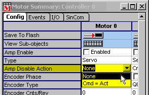
- Set the Amp Disable Action to NONE.
The motor type cannot be set to STEPPER unless the Amplifer Disable
Action it is set to NONE.
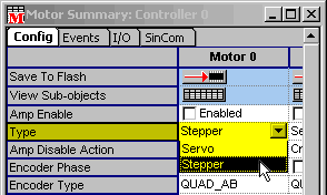
- Configure the motor Type for STEPPER.
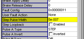
- Set the motor's Stepper Pulse Width.
When configuring the Step Pulse Width, make sure the maximum commanded
velocity does not generate a pulse period that is less than 2x
the pulse width. For example, if the maximum velocity is 100 kHz,
the pulse width must not be greater than 5 microseconds.
|
Maximum Velocity
|
Maximum Pulse Width
|
|
5 MHz
|
100 ns
|
|
2.5 MHz
|
200 ns
|
|
1 MHz
|
500 ns
|
|
500 kHz
|
1 µs
|
|
250 kHz
|
2 µs
|
|
100 kHz
|
5 µs
|
|
50 kHz
|
10 µs
|
|
25 kHz
|
20 µs
|
|
10 kHz
|
50 µs
|
|
...
|
...
|
|
500 Hz
|
1 ms
|
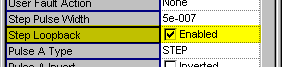
- Enable the motor's Stepper Loopback if there is no encoder
feedback.
When using pulse outputs, the quadrature encoder inputs are still
available. The position feedback information is not used to correct
the pulse motor's position, but can be used by an application
to monitor the actual position of the motor. If the encoder feedback
is not in a one-to-one ratio with the step motor resolution, be
sure to disable the position error limit action. If you do not
have an encoder, the feedback can be simulated by enabling the
motor's loopback feature.
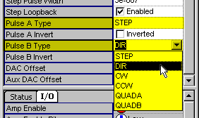
- Configure the motor's Stepper Pulse A and Pulse B Ttypes.
Pulse A and Pulse B determine the types of output pulses to be
sent to a pulse drive. The most common examples are listed in
the table below.
|
Desired Output
|
Pulse A
|
Pulse B
|
| Step and Direction |
STEP
|
DIR
|
Clockwise and
Counter-clockwise |
CW
|
CCW
|
| Quadrature |
QUAD_A
|
QUAD_b
|
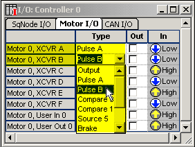
- Select the motor I/O's Configuration Type for Pulse A and
Pulse B signals.
This will route Pulse A and Pulse B signals to the node's digital
outputs.
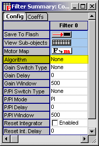
- (Optional) Set the control algorithm to NONE for optimum
firmware performance.
|
Pulse Configurations in Motion Console
Motor Object
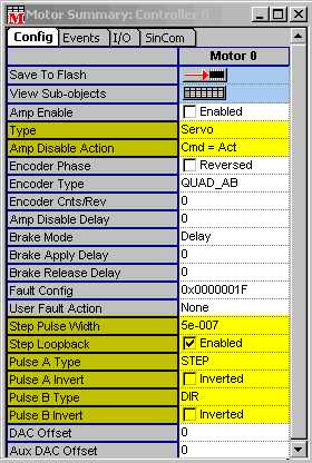
| Type |
Stepper (default is Servo) |
| Amp Disable Action |
None (default is Cmd = Act) |
| Step Pulse Width |
Value is determined by pulse drive specifications |
| Step Loopback |
Enable for open loop, Disable (default) for encoder
feedback |
| Pulse A Type |
Configure for STEP, DIR, CW, CCW,
QUADA, or QUADB |
| Pulse A Invert |
Enable or Disable |
| Pulse B Type |
Configure for STEP, DIR, CW, CCW, QUADA, or QUADB |
| Pulse B Invert |
Enable or Disable |
In the screenshot above (SynqNet-RMB-10V2), you can
configure Motor 0, XCVR A-F to be either Pulse A or Pulse B. Normally,
two bits must be configured as Pulse A and Pulse B.
| I/O Bit N Type |
Pulse A or Pulse B
(routes Pulse A signal to node's digital output)
-OR-
(routes Pulse B signal to node's digital output) |
Filter Object
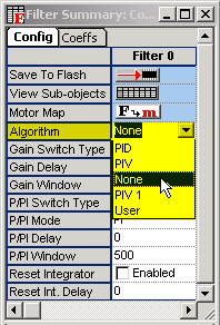
| Algorithm |
None (for optimum firmware performance) |
MPI Example
See the sample application stepCfg.c
for details.
MPX Example
| |
Controller.Axis(0).MotorType = mpiMotorTypeStepper
'AmpDisableAction set automatically when setting MotorType
Controller.Axis(0).StepPulseWidth = 0.000001 '1 us
Controller.Axis(0).StepLoopback = True
Controller.Axis(0).StepPulseAType = mpiStepperPulseTypeStep
Controller.Axis(0).StepPulseBType = mpiStepperPulseTypeDir
Controller.Axis(0).IoConfig(mpiMotorIo0) = mpiIoConfigPulseA
Controller.Axis(0).IoConfig(mpiMotorIo1) = mpiIoConfigPulseB
Controller.Axis(0).FilterAlgorithm = mpiFilterAlgorithmNone
|
See Also
Introduction to Pulse
MPIMotorConfig
MPX Axis Object Documentation
|

