Capture Objects
Introduction
A Capture object manages a single position capture logic block. It represents the physical hardware capture logic and data. When configured and armed, the capture logic block can latch a motor's position based on one or more source input triggers.
The Capture object's number, motor input trigger sources, edge, type, feedback source, and capture index are all configurable. There are two capture types: Position-based and Time-based. The capture methodologies for these types differ and can affect performance. The table below summarizes Position-based and Time-based methodolgies and their best use.
| Capture Type | Methodology | Best Use |
|---|---|---|
| Position-based | Position counters are latched in the FPGA and are read directly by the controller. | Works well for incremental quadrature encoders. |
| Time-based | FPGA latches the clock and the controller reads the clock value and position value for that sample period. The position value is interpolated by the controller from the sample's present and previous position, and the clock data. |
Works very well for any node with Drive Feedback (cyclic feedback data that is digitally transmitted from the drive to the FPGA). |
Note: Many drives have a proprietary serial encoder that decodes the encoder position and sends the position information to the FPGA once per sample. In these cases, time-based capture is more accurate than position-based capture.
For the Position type, the motor number for the input sources and the feedback motor number must be the same.
For the Time type, the motor number and feedback motor number can be different. This makes it possible to use inputs from one node to capture positions on another node.
When using captures, the controller must have enough enabled captures to process the specified capture number. The controller will process the enabled captures (captureCount) every sample period. Since each capture object is configurable, use the minimum number of captures possible for best controller performance. For example, if you want to use 2 captures for motor 0 and motor 3, set the capture count to 2 and use capture number 0 and 1.
NOTE: Time-based capture will only work correctly if the speed of an axis is less than 344 million counts per second.
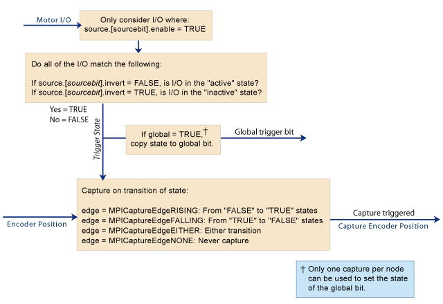
For an overview of the Capture Engine, see diagram below.
See Also: Overview of Capture
| Error Messages |
Methods
| Create, Delete, Validate Methods | ||
| mpiCaptureCreate | Create Capture object | |
| mpiCaptureDelete | Delete Capture object | |
| mpiCaptureValidate | Validate Capture object | |
| Configuration and Information Methods | ||
| mpiCaptureConfigGet | Get Capture configuration | |
| Set Capture configuration | ||
| mpiCaptureStatus | Get status of Capture | |
| mpiCaptureConfigReset | ||
| Action Methods | ||
| mpiCaptureArm | Arm capture object | |
| Memory Methods | ||
| mpiCaptureMemory | Set address to Capture memory | |
| mpiCaptureMemoryGet | Copy Capture memory to application memory | |
| mpiCaptureMemorySet | Copy application memory to Capture memory | |
| Relational Methods | ||
| mpiCaptureControl | ||
| mpiCaptureNumber | Get index of Capture (for Control list) | |
Data Types
| MPICaptureConfig | ||
| MPICaptureEdge | ||
| MPICaptureMessage / MEICaptureMessage | ||
| MPICaptureSource | ||
| MPICaptureState | ||
| MPICaptureStatus | ||
| MPICaptureTrigger | ||
| MPICaptureTriggerGlobal | ||
| MPICaptureType |
Constants
| MPICaptureNOT_MAPPED |


