TSIO-4002; Digital Output
4 Channels of 5Vdc/20mA Output
|
|
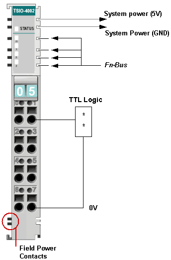
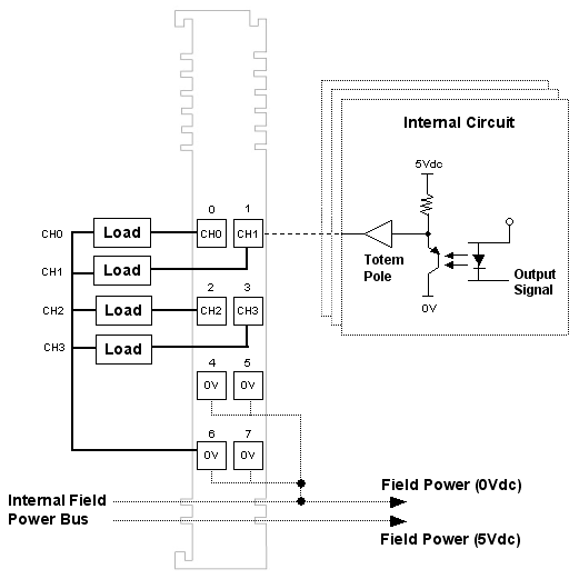
- The module has 4 Channels of CMOS Non-Inverting Output for 5Vdc/20mA.
- The connected load is switched via the digital output from the
control system.
- All outputs are electronically short-circuit protected.
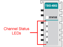
- The module has 5 status LEDs.
(1- network status, 4- field device status)
- Each output is electrically isolated from the controller by the
use of a photocoupler.
- NOTE: For MPI versions prior to the 03.04.00, the TSIO-4002 will operate correctly, but the product identification and model name will not be properly displayed.
|
| Output Specification
|
| Outputs per module |
4 channels isolated, CMOS Non-Inverting Output
(Default 0V). |
| LED Indicators |
4 green for input status
1 green/red for slice status |
| ON-state Voltage Range |
5Vdc nominal
4.5Vdc ~ 5.5Vdc |
| High-level Output Voltage |
Min. 4.5Vdc @ 5Vdc, 5mA (Note 1) |
| Low-level Output Voltage |
Max. 0.3Vdc @ 0Vdc, 5mA (Note 1) |
| Output Signal Delay |
OFF to ON: 0.3ms Max.
ON to OFF: 0.3ms Max. |
| Output Current Rating |
Max. 20mA per output,
Max. 80mA per common |
Protection
|
Short Circuit Protection: Output Signal Shutdown
Field Power Over Voltage Protection (about 6Vdc)
Field Power Reverse Voltage Protection
|
| Surge Current |
40mA for 10ms, repeatable every second |
NOTE 1: The TSIO-4002 module has a 5Vdc totempole output instead of an open-drain/source.
|
| General Specification |
| ID |
0x000F0081 |
| Logic Power Dissipation |
Max. 50mA @ 5.0Vdc |
| Isolation |
I/O to Logic: Photocoupler
isolation
Isolation Voltage: 1250Vrms/Vac
Field Power: No isolation |
Field Power
(Internal Power Bus) |
Supply Voltage: 5Vdc nominal (Note 2)
Voltage Range: 4.5 ~ 5.5Vdc
Power Dissipation: 5mA @ 28.8Vdc / channel |
| I/O Cables |
Max. AWG 14 |
| Weight |
70g |
| Module Size |
99mm x 12mm x 70mm
(H x W x L) |
| Environmental Requirements |
See Environment Requirements |
NOTE 2: The Field Power must be 5Vdc nominal. It is strongly recommended that the Field Power Distributor (TSIO-8002) be used for the TSIO-4002. |
Pinouts
 |
|
Pin No.
|
Description
|
|
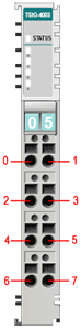
0
|
Out 0, Output Channel 0 |
|
1
|
Out 1, Output Channel 1 |
|
2
|
Out 2, Output Channel 2 |
|
3
|
Out 3, Output Channel 3 |
|
4
|
Field Ground (0V) |
|
5
|
Field Ground (0V) |
|
6
|
Field Ground (0V) |
|
7
|
Field Ground (0V) |
|
Parameters
Parameter |
Access |
Bits |
Description |
Default |
0
|
Read
and
Write
|
0-3 |
Fault Action (channels 0 to 3)
0: Fault Value (see parameter 1)
1: Hold Last State |
0
(Fault Value)
|
4-7 |
Reserved |
0 |
1
|
Read
and
Write
|
0-3 |
Fault Value (channels 0 to 3)
0: OFF
1: ON |
0
(OFF)
|
4-7 |
Reserved |
0 |
See Also: Slice Parameters
Memory
This slice does not support any memory registers.
See Also: Slice Memory
I/O Data
| |
Output Data |
Bit No. |
Bit 7 |
Bit 6 |
Bit 5 |
Bit 4 |
Bit 3 |
Bit 2 |
Bit 1 |
Bit 0 |
Byte 0 |
Not Used |
CH3 |
CH2 |
CH1 |
CH0 |
|
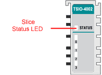
Slice Status LED
State |
LED |
Description |
Not Powered,
Not Initialized |
OFF |
The slice is either not powered or has not been initialized. |
| Normal Communication |
Green
|
Slice to network adapter communication is operating normally. |
| Communication Ready |
Flashing Green |
Slice to network adapter communication is ready to be started. |
| Communication Fault |
Flashing Red |
Slice to network adapter communication has a fault. |
| Slice Fault |
Red |
The slice has a fault. |
Channel Status LED
The TSIO-4003 has 4 Channels.
|
State
|
LED
|
Indicates
|
| Signal OFF |
OFF |
Normal Operation (Active) |
| Signal ON |
Green
|
Normal Operation (Inactive) |
|

