
|
|
| . |
S200: J1
|
|||||||||||||||||||||||||||||||||||||||||||||||||||||||||||||||||||||||||||||||||||||||||||||||||
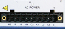 |
See Connector Locations. |
See AC Input Drive Wiring Diagram.
|
The S200 AC input drives are capable of direct line operation. All units are fully isolated and do not require external isolation transformers. The inrush current on the connection to the line is internally limited to a safe level for the drive. There are no voltage selection or ranging switches required to operate within the specified voltage input ranges.
The S200 series drives are functionally compatible with all standard forms of three-phase AC lines:
|
NOTE: The customer is responsible for supplying the appropriate fuses or circuit breakers in the J1 AC motor power lines to comply with local electrical codes.
The control input power required is between 5 and 10 watts. The AC input motor power depends on output power and the losses in the power stage.
See Regulatory Information for details.
Warnings
To avoid damage to the connector and drive, NEVER plug or unplug the J1 connector with power applied.
PE (Physical Earth)
This chassis ground point must be connected to Protective Earth ground. The connection at the Protective Earth ground end must be hard wired (do not use a pluggable connection). A ground fault detector (RCD) cannot be depended on for safety.
REGEN
Connection for an optional regeneration power resistor to absorb regenerated energy from the motor. Models S20260 and S20360 typically use 36 Ω. S20660 typically uses 12.5 Ω, although other values within the minimum resistance specification can be used. Use a wire wound resistor with 1500 Vrms isolation between terminals and case. Many applications do not require a regen resistor. If over-voltage faults occur during motor deceleration, then more kinetic energy is being returned to the bus capacitors than they can handle. Connect the proper ohmage 50 to 300 watt power resistor from this terminal, to terminal J1-4 (+BUS) in order to eliminate the over-voltage faults.
The power rating of the regen resistor depends on the amount of regenerated energy that needs to be dissipated.
Warning:
The regen input is not short circuit protected. The regen resistance MUST be within specified ranges to prevent damage to the drive. For example, between 25 to 50 Ω for the S20260 and S20360 drives.
–BUS
The -BUS terminal is usually left open during normal operation. In special multi-axis applications, drive buses can be wired in parallel to allow returned energy from one motor to power another and limit high regen powers.
NOTE: After powering down the drive, monitor the BUS voltage by connecting a meter from J1-4 (+BUS) to J1-3 (-BUS) to verify that the internal BUS capacitors have discharged prior to working on the drive. For safety, either mount the external resistor on a grounded panel or wire it to a grounded connection. The terminals of the resistor MUST NOT be grounded.
Warning: Wait 5 minutes after power is removed for the bus cap voltage to decay to a safe level before touching the regen resistor or wiring. Monitor the voltage on the bus caps with a voltmeter from +BUS (J1-4) to -BUS (J1-3).
+BUS
The +BUS terminal is used with the J1-2, REGEN, terminal to add a regen resistor to the drive to absorb regenerated energy.
NOTE: After powering down the drive, monitor the BUS voltage by connecting a meter from J1-4 (+BUS) to J1-3 (-BUS) to verify the internal BUS capacitors have discharged prior to working on the drive. For safety, either mount the external resistor on a grounded panel or wire it to a grounded connection. The terminals of the resistor MUST NOT be grounded.
Warning: Wait 5 minutes after power is removed for the bus cap voltage to decay to a safe level before touching the regen resistor or wiring. Monitor the voltage on the bus caps with a voltmeter from +BUS (J1-4) to -BUS (J1-3).
CTRL VAC
These terminals connect 120/240 VAC power to the drive’s control voltage power supply. These terminals are NOT connected to the bus power L1, L2 (J1-8,9) inside the drive.
Input Voltage Range (RMS) |
85 VAC to 265 VAC single phase 47 to 63 Hz 120 VDC to 375 VDC |
Inrush Peak Current |
10 A 0-p with 240 VAC Input |
Inrush Pulse Width |
1.60 ms |
Fusing |
Bussmann MDA – ½ |
240 VAC
240/120 VAC HOT
240/120 VAC NEUTRAL
These terminals connect 120/240 VAC power to the drive’s output power stage BUS. For single-phase operation, 120/240 use inputs J1-8, L2, and J1-9, L1.
NOTE: For maximum ride through capability, a 240 VAC input is recommended.
Input Voltage Range |
90 to 265 VAC |
Phases |
1 or 3 |
Transformer |
2 to 3 KVA – recommended KVA if transformer is required |
| Maximum AC Line | 100 KVA1 |
Parameter |
S20260 |
S20360 |
S20660 |
Worse Case Inrush Peak Current at 240 VAC |
140 A 0-p | 140 A 0-p | 240 A 0-p |
| Inrush pulse width | 1.5 ms | 1.5 ms | 2.0 ms |
Parameter |
S20260 |
S20360 |
S20660 |
Type – 250 VAC Time Delay Fuse |
|||
| 240 VAC 3 Phase (ARMS) | Bussmann MDA-5 | Bussmann MDA-8 | Bussmann MDA-15 |
| 240 VAC 1 Phase (ARMS) | Bussmann MDA-5 | Bussmann MDA-10 | Bussmann MDA-20 |
| 120 VAC 1 Phase (ARMS) | Bussmann MDA-5 | Bussmann MDA-10 | Bussmann MDA-20 |
Screw Terminal Connector
12 – 24 AWG Wire Range, Phoenix MSTB2,5/9-STF-5,08-BK
Spring Cage Clamp Connector
12 – 24 AWG Wire Range, Phoenix FKC 2,5/9-SFT-5,08-BK
Crimp Connector
Crimp Shell
14 – 20 AWG Wire Range, Phoenix MSTBC 2,5/9-STZF-5,08-BK
Crimp Contact
14 – 16 AWG Wire Range, Phoenix MSTBC-MT 1,5-2,5
Crimp Contact
18 – 20 AWG Wire Range, Phoenix MSTBC-MT 0,5-1,0
For more information, see www.phoenixcon.com.
| | | Copyright © 2001-2021 Motion Engineering |
