|
|
| . |
TSIO-7004; Analog Output2 Channels of -10~10V, 12bit Voltage Output
|
||||||||||||||||||||||||||||||||||||||||||||||||||||||||||||||||||||||||||||||||||||||||||||||||||||||||||||||||||||||||||||||||||||||||||||||||||||||||||||||||||||||||||||||||||||||||||||||||||||||||||||||||||||||||||||||||||||||||||
 |
|
Parameter |
Access |
Bits |
Description |
Default |
0
|
Read
and Write |
0-1 |
Fault Action for Channel 0: 00: Fault Value |
0 (Fault Value) |
2-3 |
Fault Action for Channel 1: 00: Fault Value |
0 (Fault Value) |
||
4-7 |
Reserved | 0 |
||
1 |
Read and Write |
0-7 |
Reserved | 0 |
2 |
Read and Write |
0-7 |
Channel 0 Fault Value Low Byte | 0 |
3
|
Read
and Write |
0-3 |
Channel 0 Fault Value High Byte | 0 |
4-7 |
Reserved | 0 |
||
4 |
Read and Write |
0-7 |
Channel 1 Fault Value Low Byte | 0 |
5
|
Read
and Write |
0-3 |
Channel 1 Fault Value High Byte | 0 |
4-7 |
Reserved | 0 |
Memory |
Access |
Bits |
Description |
Default |
0
|
Read
|
0-7 |
Channel 0 Output Data Low 8 bits | |
1
|
Read
|
0-3 |
Channel 0 Output Data High 4 bits | |
4-7 |
Not Used | 0 |
||
2
|
Read
|
0-7 |
Channel 1 Output Data Low 8 bits | |
3
|
Read
|
0-3 |
Channel 1 Output Data High 4 bits | |
4-7 |
Not Used | 0 |
||
4
|
Read
|
0-7 |
Reserved | 0 |
5
|
Read
|
0-7 |
Reserved | 0 |
6
|
Read
and Write |
0-7 |
Fault Action (Same as parameter 0) |
0 |
7
|
Read
and Write |
0-7 |
Reserved |
0 |
8 |
Read and Write |
0-7 |
Channel 0 Fault Value Low Byte (Same as parameter 2) |
0 |
9
|
Read
and Write |
0-7 |
Channel 0 Fault Value High Byte (Same as parameter 3) |
0 |
10 |
Read and Write |
0-7 |
Channel 1 Fault Value Low Byte (Same as parameter 4) |
0 |
11
|
Read
and Write |
0-7 |
Channel 1 Fault Value High Byte (Same as parameter 5) |
0 |
Output Data (SynqNet) |
|
|||||||||||||
Output Data (CANopen) |
|
|||||||||||||
| NOTE: The resolution of this slice is 12 bits so the 3 lsb are not used. |

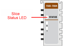
State |
LED |
Description |
| Not Powered, Not Initialized |
OFF | The slice is either not powered or has not been initialized. |
| Normal Communication | Green |
Slice to network adapter communication is operating normally. |
| Communication Ready | Flashing Green | Slice to network adapter communication is ready to be started. |
| Communication Fault | Flashing Red | Slice to network adapter communication has a fault. |
| Slice Fault | Red | The slice has a fault. |
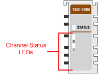
The TSIO-7004 has 2 Channels.

|
State
|
LED
|
Indicates
|
| Signal OFF | Green | Normal Operation (Active) |
| | | Copyright © 2001-2021 Motion Engineering |