|
|
| . |
TSIO-1002; CAN Network Adapter
|
|||||||||||||||||||||||||||||||||||||||||||||||||||||||||||||||||||||||||||||||||||||||||||||||||||||||||||||||||||||||||||||||||||||||
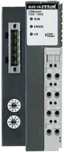 TSIO-1002 |
|
For more information, please see the SynqNet I/O Quick-Start Guide.
| Communication Interface Specifications | |
| Number of network nodes on a single bus | Max. 99 |
| Max. Number of slices per Network Adapter |
32 (Additional system power may be required) |
| Peripheral Signals | Input 64 byte / Output 64 byte |
| LED Indicators | 1 green: CAN-RUN status indicator 1 red: CAN-ERR status indicator 1 red/green: I/O status indicator 1 green: Field Power Supply status indicator |
| Bit Rate | 1Mbit, 800k, 500k, 250k, 125k, 50k, 20k, 10k |
| Max. Number of I/O bits per CAN Network Adapter |
64 digital inputs 64 digital outputs 64 analog inputs (4 * 16-bit channels) 64 analog outputs (4 * 16-bit channels) |
| Max. Bus Length | Depending on Bit rate |
| Number of PDOs available (Process Data Objects) |
8 Transmit PDOs 8 Receive PDOs |
| Number of SDOs available (Service Data Objects) |
1 Standard SDO |
| General Specifications | |
| System Power | Supply Voltage: 24Vdc nominal Voltage Range: 11~28.8Vdc |
| Power Dissipation | Nominal 24Vdc @ 100mA |
| Current for I/O Module | Max 5Vdc @ 1.5A |
| Isolation | Network to Logic: Isolation Logic to Field Power: Isolation Logic to System Power: No isolation |
| Field Power | Supply Voltage: 24Vdc nominal Voltage Range: 11~28.8Vdc |
| Current of Jumper Contacts | DC 10A maximum capacity |
| Max. Number of SLICE modules per Network Adapter |
Software dependent |
| I/O Cables | Max. AWG 14 |
| Weight | 150g |
| Module Size |
42mm x 67mm x 95mm |
The two switches on the network adapter are used to set the bit rate and node address.
Setting the Bit Rate
|
|
|
Setting the Node Address
|
|
|
No. on Dial
|
Bit Rate
|
|
0
|
1Mbit
|
|
1
|
800k
|
|
2
|
500k
|
|
3
|
250k
|
|
4
|
125k
|
|
5
|
100k
|
|
6
|
50k
|
|
7
|
20k
|
|
8
|
10k
|
|
9
|
Auto Detect
Bit Rate |
|
State
|
LED
|
Indicates
|
| Not Powered, Not On-line |
OFF | The Device is not on-line or may not be powered on. |
| On-line, STOPPED |
Single flash Green |
The Device is in the STOPPED state. |
| On-line, PRE-OPERATIONAL |
Blinking Green | The Device is in the PRE-OPERATIONAL state. |
| On-line, OPERATIONAL |
Green ON | The Device is in the OPERATIONAL state. |
|
State
|
LED
|
Indicates
|
| Not Powered, Not On-line |
OFF | The Device is not on-line or may not be powered. |
| Warning Limit Reached On-line |
Single flash Red | At least one of the error counters of the CAN controller has reached or exceeded the warning level (too many error frames). |
| Error Control Event On-line |
Double flash Red | The guarding monitor has asserted, guarding telegrams are no longer being received. The adapter is in a pre-operational state. |
| Sync Error On-line |
Triple flash Red | A sync error has occurred. - The adapter is pre-operational (PDOs are switched OFF). |
| Bus OFF | Red ON | Device is in the cyclic data exchange mode with the parameterization master. |
|
State
|
LED
|
Indicates
|
| Not Powered, No Expansion Module |
OFF | Device has no expansion module or the device may not have power. |
| Fn-Bus On-line, Not Exchanging I/O |
Flash Green |
Fn-Bus is active, but no I/O data is being passed from the expansion module. |
| Fn-Bus Connection, Run Exchanging I/O |
Green | Expansion slot is connected and exchanging I/O data. |
| Fn-Bus Connection Fault, During Exchange of I/O | Red |
One or more expansion modules is in a fault state. - Fn-Bus communication failure. |
| Expansion Configuration Failed | Flash Red |
Failed to initialize the expansion module. |
|
State
|
LED
|
Indicates
|
| No Field Power | OFF | No field power. |
| Supplied Field Power | Green |
24Vdc Field Power is being supplied to the network adapter. |
| | | Copyright © 2001-2021 Motion Engineering |