Connect to Digital Quadrature Encoders
Encoder Wiring
|
Note
|
The
100 ohm terminations to the receivers are software-selectable. If
you use the Scale Interpolation Module (SIM), you must program
the 100 ohm terminations off, i.e., remove them from the circuit.
To learn more about encoder termination, please refer to SIM4 Option.
|
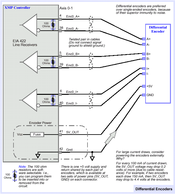
Connect to Differential Encoders
Connect to differential encoders
(digital).

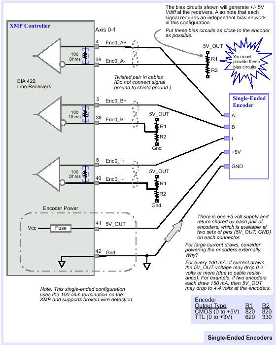
Connect to Single-ended Encoders
|
Note
|
To
connect the XMP's differential line receivers to single-ended encoders,
you must add a pair of resistors (R1, R2) in the configuration shown,
to bias the negative end to the middle of the encoder's output voltage
range.
|
Connect to single-ended encoders
(digital).

Broken Wire and Illegal State
Detection
The encoder inputs (channel A+, A-, B+, B-) are monitored by the FPGA
(an on-board logic component). The encoder inputs are sampled at 20MHz.
By default, a digital filter is applied to each encoder input. This digital
filter requires that an encoder input (channel A+, A-, B+, B-) be stable
for 4 clock cycles (200 nanoseconds) before a transition is recognized,
i.e., encoder input states lasting less than 4 clock cycles are filtered
out. This means that the absolute maximum encoder rate is 10 million counts/sec
with digital filtering enabled.
Previous | Next
|
