Configuring Analog Connections
This section provides more general guidance for configuring
analog controllers with various hardware (servo amps; encoders, etc.).
XMP-PCI, XMP-CPCI
Connections to Servo Motors
XMP-series controllers can control brush servo motors,
brushless servo motors, or linear brush/brushless motors. Basic connections
require an analog output signal (from the controller to the amplifier)
and an encoder input (from the motor to the controller).
Most amplifiers support either Velocity mode (voltage
control) Torque mode (current control) or both. The XMP controller can
be used with either servo motor/amplifier package.
XMP-series controllers accept RS-422 compatible (0V
to +5V, 40mA max) encoder input from either differential or single-ended
encoders. Differential encoders are preferred due to their excellent noise
immunity. The connections for a single-ended encoder are identical to
a differential encoder except that references must be connected to channel
A- and channel B-.
The controller reads the index pulse (either single-ended
or differential ended). Typically, there is one index pulse per revolution
of the encoder (rotary type), which can be used for homing. Encoder signals
are read in quadrature. Every line on the encoder will produce a rising
edge and a falling edge on channels A+ and B+ which is interpreted by
the XMP controller as four encoder counts.
Brush Servo Motors
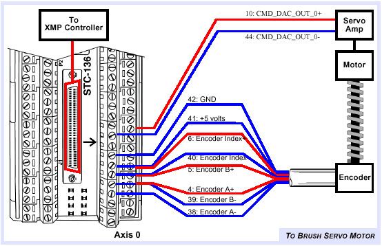
The minimum required connections to brush-type servo
are: Analog signal ( ± 10V), +5V, Signal Ground, Encoder Channel A+, Encoder
Channel B+. Typical connections for a brush servo motor with a differential
encoder follow.
Typical brush servo motor connections.
|
Note
|
Any unused lines should be left unconnected.
|
Brushless Servo Motors
Typical connections for a brushless servo motor with
a differential encoder are:
Typical brushless servo motor
connections.
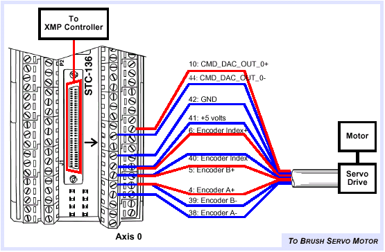
Typical brushless servo motor drives of this configuration
are "intelligent." If single ended encoders are used, external references
will need to be supplied.
Step-and-Direction Controlled Servo Motors
Some brushless servos are controlled by step-and-direction
pulses. With this scheme, the position information is communicated by
step pulses, and the PID loop is handled internally by the drive itself.
Connections to Step Motors
Open-loop Step Motors
XMP controllers can control step motors in open-loop
(no feedback) configurations. The XMP can also be configured for STEP
LOOPBACK. When this is enabled, the motor Position Error Limit and Axis
Settling will depend on the output steps being read back into the actual
position register. If STEP LOOPBACK is disabled, an external feedback
device (e.g. encoder) will be needed for determining position error limits
and axis settling. In either case, the output is generated regardless
of actual position.
Typical open-loop step motor connections for step drives
triggering on the rising edge.
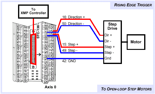
For stepper drives that trigger on the falling edge,
invert the step output transceiver. This can be done from Motion Console
by enabling the XCVR A: Invert (or XCVR B: Invert, etc.) parameter in
the Motor Summary / I/O page.

|
Note
|
To determine whether your drive triggers on the rising or falling
step edge, consult the drive manufacturer's manual.
|
Connections for Dual-loop Control
XMP-series controllers can be configured for dual-loop
control. In dual-loop control, the velocity information for the PID derivative
term (Kd) is derived from a rotary encoder on the motor shaft, and the
position information for the PID proportional and integral terms is derived
from an encoder on the load itself.
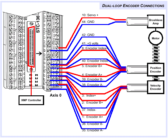
The axis that will be used for the rotary encoder is
configurable through software and can be any axis that is not controlling
a motor. For example, if axis 0 is configured for velocity feedback and
axis 1 is configured for positional feedback, your system would be connected
as shown in the next figure.
Dual-loop encoder connections
with differential encoders.
MPI Support for Steppers
Support for stepper motor control is included within
the MPI (Motion Programming Interface).
Transceivers
All transceiver and user I/O are part of the "Motor"
object. Each hardware axis has three (3) transceivers dedicated to it,
labeled XCVRA, XCVRB, and XCVRC. The XCVRA, XCVRB, and XCVRC transceivers
support:
All three transceivers support input/output,
normal/inverted
|
Transceiver
|
Input
or Output?
|
Normal
or Inverted?
|
|
XCVRA
|
Yes
|
Yes
|
|
XCVRB
|
Yes
|
Yes
|
|
XCVRC
|
Yes
|
Yes
|
A and B transceivers support more features
|
Transceiver
|
Step
or Dir?
|
CW
or CCW?
|
Quad
A or Quad B?
|
Normal
or Inverted?
|
Compare?
|
|
XCVRA
|
Yes
|
Yes
|
Yes
|
Yes
|
No
|
|
XCVRB
|
Yes
|
Yes
|
Yes
|
Yes
|
No
|
|
XCVRC
|
No
|
No
|
No
|
Yes
|
Yes
|
Note that only sensible XCVRA/XCVRB configurations
are permitted. For example, if XCVRA is configured for Step, then XCVRB
should be configured for Dir. If XCVRA is configured for Dir, then XCVRB
should be configured for Step. Refer to the next table.
Transceiver configurations that are
supported
|
XCVRA
|
XCVRB
|
XCVRC
|
|
Step
|
Dir
|
|
|
Dir
|
Step
|
|
|
CW
|
CCW
|
|
|
CCW
|
CW
|
|
|
QuadA
|
QuadB
|
|
|
QuadB
|
QuadA
|
|
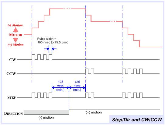
Step/Dir & CW/CCW Specifications
Step/dir and CW/CCW specifications
|
Pulse width range for Step, CW & CCW
|
100 nsec to 25.5 microsec
|
|
Maximum duty cycle must be less than
|
50% (or 25.5 microsec)
|
|
Minimum separation between Dir edge and rising
Step edge (or between CW and CCW edges)
|
125 nanosec
|
|
Maximum step output rate
|
2.5 MHz
|
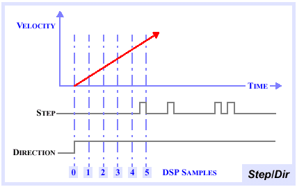
The maximum separation between the Dir edge and the
rising Step edge depends upon the sample rate and the commanded motion.
A rule of thumb is that the Dir edge occurs at the start of the DSP's
trajectory calculator (when the command velocity is non-zero), and the
first Step occurs when the command position increments the first whole
count. The time separation can be estimated from the commanded acceleration
(Accel):

For example, if acceleration is 100,000 cts/sec2, then
the separation between the Dir edge and the first Step edge is

which computes to Time = 4.5 milliseconds
The minimum separation between the Dir edge and the
first Step edge is 125 nanoseconds. Note that the XMP increments its counter
on each rising edge of the Step or CW signal.
Step/dir (and CW/CCW) and motor
motion.
Step/dir and velocity.
Stepper Loopback
When the Loopback feature is enabled, the
Step/Dir (or CW/CCW) logic is routed back into the encoder inputs. Note
that the DSP doesn't use the feedback for control. There are two to three
samples of latency between when the DSP's command position is updated
and when the actual position (loopback) is updated. Also, loopback is
not affected by "inverted" configurations.
The position error limit is still valid
for loopback operations. If Loopback is not enabled, you can connect the
encoder inputs to actual encoders.
HELPFUL TIP: Stepper loopback is
very useful for motor simulation. When real servo motors are not available,
the controller's stepper motor and loopback configurations make it possible
to develop software.
Closed Loop Steppers
Currently, there is no explicit support
for closed loop stepper configurations. But, it is possible to correct
the final position based on the actual position via application software,
since the encoder inputs are valid with Step/Dir and CW/CCW configurations.
Stepper Configuration using Motion Console
To configure a Stepper using Motion Console,
you must set the following parameters:
Parameters used to configure a stepper
in Motion Console
|
Object
|
Motion
Console Parameter
|
Setting
|
|
Motor
|
Type
|
Stepper
|
|
|
Stepper
pulse width
|
2.55
(10-5)
|
|
|
Stepper
loopback
|
Yes
|
|
|
Transceiver
A config
|
Step
or CW
|
|
|
Transceiver
B config
|
Dir or
CCW
|
|
Filter
|
Algorithm
|
None
|
Previous | Back to Main Menu
|
