XMP-CPCI-3U Bus

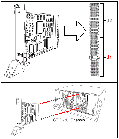
The four-axis CPCI-3U is a smaller version of the -6U
board. It connects to the backplane via two connectors: J1 and J2 (see
figure above). Motion drive I/O is conveyed via J2. For more information,
click here. Connector J1 is reserved
as a computer bus, and is described in this section.
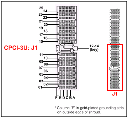
Backplane connector pins are referred to by numbered
rows and lettered columns as shown below:

CPCI-3U Main Board, Rear Panel Connector J1:
User I/O
NOTE: the CPCI XMP does not use
the 64-bit extension.
CPCI backplane connector (main and
expansion boards)
|
Pin
|
E
|
D
|
C
|
B
|
A
|
|
25
|
5V |
3.3V |
ENUM# |
REQ64# |
5V |
|
24
|
ACK64# |
AD[00] |
V(I/O) |
5V |
AD[01] |
|
23
|
AD[02] |
5V |
AD[03] |
AD[04] |
3.3V |
|
22
|
AD[05] |
AD[06] |
3.3V |
GND |
AD[07] |
|
21
|
C/BE[0]# |
M66EN |
AD[08] |
AD[09] |
3.3V |
|
20
|
AD[10] |
AD[11] |
V(I/O) |
GND |
AD[12] |
|
19
|
AD[13] |
GND |
AD[14] |
AD[15] |
3.3V |
|
18
|
C/BE[1]# |
PAR |
3.3V |
GND |
SERR# |
|
17
|
PERR# |
GND |
SBO# |
SDONE |
3.3V |
|
16
|
LOCK# |
STOP# |
V(I/O) |
GND |
DEVSEL# |
|
15
|
TRDY# |
GND |
IRDY# |
FRAME# |
3.3V |
|
12
- 14
|
Key
Area
|
Key
Area
|
Key
Area
|
Key
Area
|
Key
Area
|
|
11
|
C/BE[2]#
|
GND |
AD[16] |
AD[17] |
AD[18] |
|
10
|
AD[19]
|
AD[20] |
3.3V |
GND |
AD[21] |
|
9
|
AD[22]
|
GND |
AD[23] |
IDSEL |
C/BE[3]# |
|
8
|
AD[24]
|
AD[25]
|
V(I/O) |
GND |
AD[26] |
|
7
|
AD[27]
|
GND
|
AD[28] |
AD[29] |
AD[30] |
|
6
|
AD[31]
|
CLK
|
3.3V |
GND |
REQ# |
|
5
|
GNT#
|
GND
|
RST# |
BRSVP1B5 |
BRSVP1A5 |
|
4
|
INTS
|
INTP
|
V(I/O) |
GND |
BRSVP1A4 |
|
3
|
INTD#
|
5V
|
INTC# |
INTB# |
INTA# |
|
2
|
TDI
|
TDO
|
TMS |
5V |
TCK |
|
1
|
5V
|
+12V
|
TRST# |
-12V |
5V |
|
