Measurement-based Feedforward Tuning:
Open Loop Feedforward
To calculate the velocity feedforward, you will need
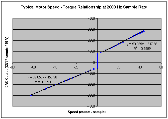
to make a plot showing the relationship between the DAC output and the
motor velocity. The velocity feedforward measurement can be taken by commanding
several closed loop velocity moves and collecting the DAC values or commanding
many open loop DAC offsets and observing the velocity. The example below
was taken with open loop DAC offsets.
The following procedure was used:
| |
- Set the DAC offset
- Wait 5 seconds for the velocity to stabilize
- Measure the velocity by collecting the encoder position
twice (one second apart).
Convert the velocity to counts/sample
- Record the velocity and DAC offset
- Increase the DAC offset
- Repeat until you reach the maximum velocity or torque
offset you are comfortable with
- Repeat for the opposite DAC offset polarity
|
Velocity feedforward on the XMP is calculated as follows:
Velocity feedforward contribution to DAC
= commanded
velocity (counts / sample) * Kvff

Note the deadband from friction. The friction feedforward
value is the average of the positive Y intercepts and the negative of
the negative Y intercept.
In this case, it is (717 – -450) / 2 = 583 = friction
feedforward value
This motor drive has an offset that can be calculated by taking the average
the Y intercepts (717 + -450) = 267.
Excel was used to get the trendlines in the forward
and reverse directions. Two things about this drive are strange:
| |
- The velocity feedforward values are slightly different in the
different directions. This is likely a commutator misalignment
issue. In this example, we are using a brushed motor, so there
is no cancelling adjustment available.
- The friction feedforward values are different in the forward
and reverse directions. This indicates a drive offset. We can
adjust this offset in the filter parameters. The drive offset
is the forward friction deadband minus the reverse friction deadband.
|
Previous | Back to Table of Contents
|

