|
|
| . |
SynqNet Node Failure
For information about packet errors, please see the Packet Error Counters section. A SynqNet Failure occurs when a node on the network reaches its FAIL threshold. The example below explains what happens on a SynqNet network when a node has reached its Fail Limit threshold.
The default, downstream
Fail Limit is when the Packet Error Rate Counter = 12 The table below shows the Packet Error Rate Counter at the controller and nodes during each controller period. For simplicity, the example below assumes that the Packet Error Counter and Packet Error Rate Counter are identical.
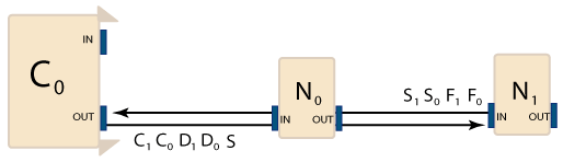
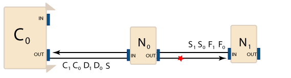
The SynqNet network is operating normally and zero packets are being lost. The next few controller periods show a problem with the downstream flow of packets from N0 to N1. Packets are not being received by N1.
The default downstream Fail Limit for each node is when the Packet Error Rate Counter = 12. In the example above, N1 reaches its Fail Limit in four consecutive cycles. Once the Fail Limit has been reached, the node will enter the SYNQ Lost State and disable its outputs. The controller stops sending packets over the network because communication has been lost with N1.
MPI Software PerspectiveNode failure tolerance is supported with string, ring, or other topologies. If one or more nodes fail, the network will continue to operate in SYNQ mode, sending and receiving data to/from the good nodes. Typically, a node failure indicates a serious problem. For instance, a broken cable in a string topology, loss of power to a node, or a large number of packet errors. A node failure is not automatically recoverable, because the state of the node is unknown and network timing schedule can only be transmitted to the node at initialization time. To recover a system with failed nodes, the node or cable hardware must be repaired or replaced and then the network must be shutdown and re-initialized. Events If a node fails, the controller will also generate a MPIEventTypeSQNODE_NODE_FAILURE status/event for each failed node. The status can be read with mpiSqNodeStatus(...) decoding the eventMask with mpiEventMaskBitGET(eventMask, MPIEventTypeSQNODE_NODE_FAILURE). The node failure event generation is configured by setting the eventMask with mpiSqNodeEventNotifySet(...). After the SQNODE_NODE_FAILURE event occurs, the status/event can be cleared with mpiSqNodeEventReset(...). This will allow another SQNODE_NODE_FAILURE status/event to be triggered after the network has been re-initialized. Node Failure Action If a node fails, the controller will automatically generate an ABORT action for the motor objects that are mapped to that node. This makes it easier for users and applications to identify node problems from the motor object. Network Shutdown Examples Ring Topology - One node fails due to loss of power
String Topology - Single cable break causing node failures
There are several other variations. The motor's nodeFailureAction feature could be used to stop the motors that are not located on the faulted node(s). Or the motor's nodeFailureAction could be used to stop a select group of critical motors. Or, the motor's nodeFailureAction could be set to NONE, allowing the application to decide how respond to node failures. The general concept is to keep as much of the network/nodes functioning as possible when failures occur. This allows an application to deal with critical axes, non-critical axes, and axis relationships differently. For example, suppose a machine has an X, Y gantry with 3 feeder axes. If the X or Y node fails, an application will want to Abort X, Y axes immediately and stop the machine operation to fix the problem. But, if a feeder axis fails, the application may want to continue X, Y control until the axes can be moved to a safe location and the feeder axes can be serviced. Expected BehaviorA node will almost always receive ALL of its packets. An acceptable Packet Error Rate is roughly 0-1 errors per day. However, if you are experiencing one or more errors per hour, you should definitely check the data integrity of your system. A high error rate is almost always caused by a faulty cable/connector or a bad connection. Troubleshooting
|
|||||||||||||||||||||||||||||||||||||||||||
| | | Copyright © 2001-2021 Motion Engineering |