XMP-Analog Architectural Overview
Introduction
This section provides a general description of the XMP
controller's architecture. It is intended to help users better understand
the XMP's inner workings, and also explains how hardware functions with
external components such as host computers, drives, and encoders.
Architectural Overview
The XMP-Analog controller is a remarkably integrated
device, designed to link a host computer with industry-standard motion
drives. While many motion controllers heavily task the host computer's
CPU to calculate motion paths and execute commands, the XMP performs much
like a computer-within-a-computer to free the host of these tasks. Because
the controller dedicates itself 100 percent to the task of motion control,
the host computer is tasked only with communicating high-level commands;
it remains free to oversee other tasks. Meanwhile, your machine's motion
drive is ensured the safest, most rapid, and precise motion control possible.
The XMP controller achieves this feat through a fully integrated architecture,
consolidating all essential control components and subsystems onto one
controller.
Computer
Hosts
XMP controllers can be hosted by both PCI and CompactPCI (CPCI) computers
via a 32-bit direct memory interface. Remote hosting via an Ethernet (TCP/IP)
connection is also available.

Digital Signal
Processor (DSP)
The hardware centerpiece of the XMP is the SHARC DSP (Super Harvard ARchitecture
Computer Digital Signal Processor). By taking full advantage of the DSP's
horsepower, efficiency is optimized, by splitting the motion tasks between
the host and XMP.

Motor Control
Each controller is capable of operating up to 16 axes (independently configurable
to control a servo or stepper motor) at a sample rate of 5 KHz, or 8 axes
at a sample rate of 10 kHz. Included with each axis is a high speed compare
output, and a high speed capture or registration input. Each axis can
also be configured to sinusoidally commutate servo motors via two analog
outputs. Full tuning capability is offered with PID and advanced, post-PID
filtering options for each axis, including gain-scheduling and dual-loop
control. Stepper output rates can be as high as 2.5 MHz. This direct-digital
pulse train can control an open or closed loop motor, enabling frequency-controlled
servo operation. Axes can be configured for step-direction or clockwise-counterclockwise
operation.

Motion
Feedback
Motion feedback can be standard quadrature from an incremental encoder
(10 MHz max, 40 MHz count rate), ±10 volt analog differential signal,
or analog encoder signal routed to a 4096x Scale Interpolation Module
(SIM4).

Safety
Dedicated, DSP-based motion control optimizes safety: the controller's
on-board watchdog timers constantly monitor handshaking, and a dedicated,
general purpose E-stop input is at the ready. Each axis also has configurable,
optically-isolated software and hardware limits up to 24 volts.

Clock
A phase-locked loop (PLL) clock generator provides the master clock to
the DSP, PCI interface, state machines and FPGAs.

Analog
Power Supply
Clean analog power is generated on ±15V power rails from Vcc. Each 8-axis
controller has its own analog power supply.

XMP
Components
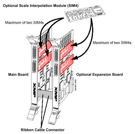
Three key components comprise the XMP family: main boards, expansion boards,
and SIM4 modules. Every XMP controller starts with one main controller.
Other components are added as needs dictate.
XMP main board
Every XMP controller consists of at least this component; in some cases
(XMP-CPCI-3U and XMP-SERCOS-PMC) it is the only component. Each main board
includes a SHARC DSP processor subsystem with up to two motion blocks
each.
XMP expansion board (optional)
Connects directly to one main board (XMP-PCI and XMP-CPCI-6U only) via
a ribbon cable. Adds up to two more motion blocks, with 4- and 8-axis
models available.
SIM4 scale interpolation module
(optional)
Plugs directly into main and/or expansion boards (XMP-PCI and XMP-CPCI-6U
only) via mezzanine connectors. Up to two SIM4s may be added to each main
or expansion board.
XMP controllers and SIM4 modules.

|
