|
|
| . |
Overview of CompareCompare Features | Compare Modes | Streaming Compare Details | Delta Compare Mode (Divide-by-N) | The Compare module generates an output signal based on comparison to a position feedback value. The compare engine monitors raw feedback in the node logic at hardware speed. When the position exceeds the compare value, the module can generate an output pulse or state on a general purpose IO pin. Each output pulse width may be controlled by time-width, or position-width. The compare module is architected for four modes: single-shot compare, streaming compare, multiple compare (sometimes called PLS), and delta compare (often called divide-by-N). Only streaming and delta modes are completed at this time. The SynqNet compare FPGA logic is controlled by both service channel configuration commands (generated by an application calling MPI methods) and cyclic data (moving streaming compare points from controller memory to the SynqNet node FPGA buffer). 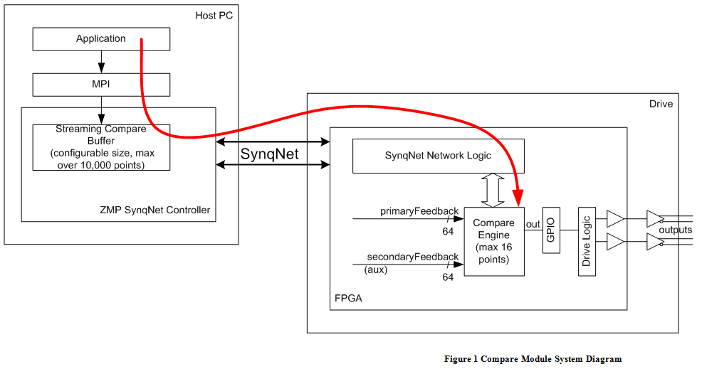 Figure 1 Compare Module System Diagram Note streaming compare mode allocates a buffer inside the SynqNet controller memory (used as a virtual FIFO). The application can preload a large number of compare points prior to a move, without any real-time constraints. The controller moves this data to the node hardware using SynqNet packets. The packet buffer may hold up to 16 values per SynqNet cycle, providing a guaranteed real-time update rate. The controller buffer size is set by the application and can exceed 10,000 points (limited only by available controller memory). The packet buffer size determines the maximum event rate. The default is 4 values per packet (typical sustained rate of 2 events per cycle). The application can use custom packet configuration functions to change the packet buffer size, up to a maximum of 16 values per packet. One Compare Module typically contains one Compare Engine, but compile-time FPGA options allow up to 8 compare engines. Each compare engine has 1 compare output, which connects to an external FPGA pin through the output multiplexer function in the GPIO (general purpose IO) module. Each compare engine can select from either the primary or secondary feedback of one motor, and may drive the GPIO outputs for that same motor only (there is no hardware method to remap outputs to any other axis or node). In addition, a time feedback option is available for debug and testing. Note the MPI compare software object is independent of the MPI motor object. This preserves the option for a Node IO design with 8 compare outputs per compare module (without requiring an MPI motor object). 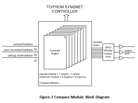 Figure 2 Compare Module Block Diagram The figure below shows the internal data flow used to support the four different modes. Details are provided in each of the following sections. 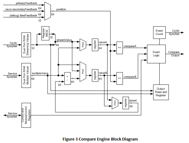 Figure 3 Compare Engine Block Diagram Compare FeaturesKey features of the compare module are listed below.
Compare ModesStreaming compare mode and Delta (Divide-By-N) compare modes are available at this time. Streaming Compare Mode Streaming compare generates a sequence of output signal pulses. This mode is used for a series of output events during a single move in one direction. Prior to the move, the MPI writes a list of compare values into a vrtual FIFO in controller memory (the buffer size is configurable and may exceed 10,000 values). Each value in the list has options for direction (less than or greater than) and output event (normally timed-width pulse or position-width pulse). Each software "comparePoint" in the list is translated into one or more hardware commands. As each command value is consumed, the next is loaded into hardware. The MPI is allowed to append additional values while the list is consumed. In the future, MPI events will be added to notify the application as the buffer is consumed (threshold event) and when the last event occurs. By default, the SynqNet controller can sustain a streaming output pulse rate of 2 time-width pulses per SynqNet cycle for example, 8,000 pulses/second with a 4 kHz sample rate (position-width pulses require 2 values per pulse, 1/2 the sustained rate). The rate can be increased with custom packet configurations. Further discussion is in the section "Streaming Compare Details". 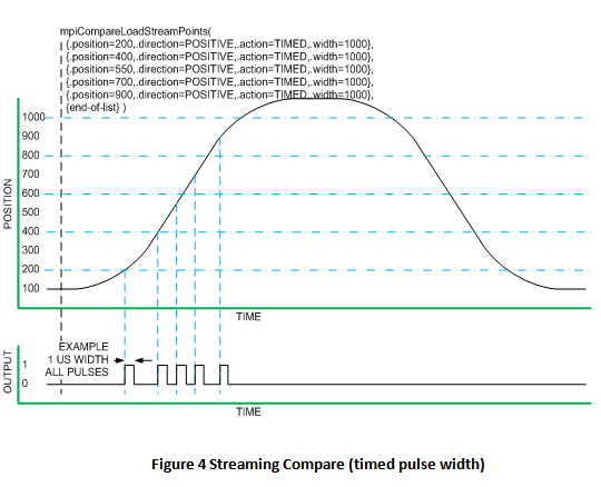 Figure 4 Streaming Compare (timed pulse width) 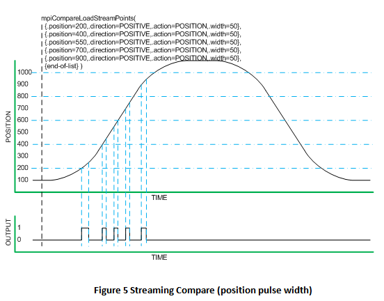 Figure 5 Streaming Compare (position pulse width) 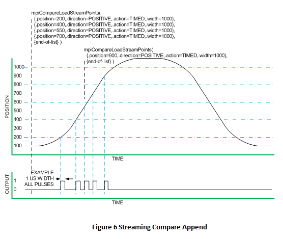 Figure 6 Streaming Compare Append The data flow for streaming compare is shown below. The OutputTimer, MS32, and LS32 values are sent via cyclic SynqNet data through the Streaming Values dual port RAM, creating a 64-bit valueA to compare against the selected position feedback. Up to 16 values (default is 4) can be sent in each SynqNet cycle (each controller sample period), depending on the configured buffer size of the compareEngineDataN packet field. The event logic checks the downstream NextWritePtr field to determine which values in the Streaming Values RAM are valid. The controller monitors the upstream EventCount to determine which values have been consumed (and when another new value can be added to the downstream buffer). The cyclic streamMode bits control the action for each value in the stream. 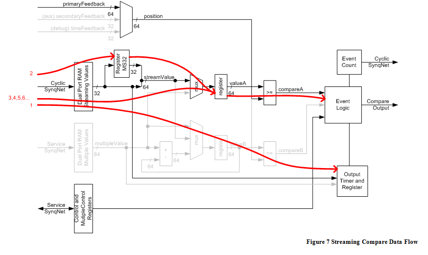 Figure 7 Streaming Compare Data Flow Programming Streaming Compare The application must configure the FPGA prior to a move using compare:
The application must set the position and action for the compare:
Each ComparePoint defines a 64-bit position, direction, action, and width (further information in "Streaming Compare Details" section). The MPI streams all these values and actions into the controller buffer memory. If the buffer fills, the MPI returns the count of values accepted, so the application can later load the remaining points. The controller firmware will set the cyclic enable bit (also allowed prior to loading points):
The compare hardware is now active and ready to trigger. The application may now command the move. As each compare position is reached, the FPGA triggers the associated output action. Each value triggers one action one time (so any jitter back and forth across a position still creates only a single output event). The controller firmware transfers compare points from the controller buffer (which is very big) into the packet buffer (typically 4 values) at the controller's cyclic sample rate, and monitors the cyclic eventCount from the FPGA to ensure each step completes. Additional compare points can be appended with the same method, either prior to the move or during the move:
The application may monitor eventCount in the status. There is no MPI method for this yet. The controller can provide a compare complete event to the application. There is no MPI support for this event yet. The application ends by disabling the compare, and optionally deleting the compare object.
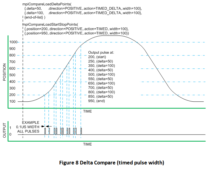
Streaming Compare DetailsEach software ComparePoint defines a 64-bit position, direction, action, and width (time in ns or position counts depending on the action type). The MPI translates this into multiple streaming cyclic commands as necessary to load the timer register, MS32 register, and LS32 compare value. For example, a ComparePoint with a timed pulse may generate a 32-bit value to set the timer pulse width (if necessary), an MS32 load (if necessary), and always generates an LS32 value. A ComparePoint with position width may generate MS32 load (if necessary), plus LS32 load for the output assert, another MS32 (if necessary), and finally an LS32 for the output negate. The MPI streams all these values and actions into the controller buffer memory. If the buffer fills, the MPI returns the count of values accepted, so the application can later load the remaining points. Note the OutputTimer and MS32 values are sent only when they change, so at maximum rate only LS32 values are sent (1 compare event per 32-bit value sent over SynqNet). At the other extreme, if different timed pulse widths are used and the MS32 changes for every event, three 32-bit values are used for each compare event. However MS32 only changes for each motor revolution, which is much slower than the cyclic data rate, so MS32 has little impact. With position-width points, two compare values per pulse are required an LS32 value for the output assert, and a second LS32 value for the output negate. This effectively halves the maximum number of pulses stored in the streaming event list buffer (and halves the maximum event rate). The peak and sustained output pulse rate is controlled by the size of the cyclic packet buffer sent over SynqNet. The controller moves values from its "virtual FIFO" buffer, into the packet buffer. The compare engine in the node sees the packet buffer as a circular buffer of values used for the raw hardware compare logic. As positions are exceeded, the engine updates its event count, which the controller will later read, telling the controller to load the next value into the packet buffer. See section "Maximum Streaming Compare Event Rate" for more specific calculations. Delta Compare Mode (Divide-by-N)Delta compare generates a series of pulses with a repeating pattern. This mode is used for a single move in one direction. The MPI loads the controller with a start position, stop position, and a pattern of delta values (1 or more repeating pulses). Each value has an associated output action (normally timed-width pulse or position-width pulse). In the most basic case, the MPI programs the start value, stop value, and 1 delta value, all using a timed pulse width. The first pulse occurs when position exceeds the start value. The FPGA hardware then adds the delta and start values to calculate the 2nd compare position. When this next position is exceeded, the delta value is added again to calculate the 3rd compare position, and the process repeats until the stop position triggers the final output event. Multiple delta values allow for a repeating sequence to be defined. This can be used to approximate a non-integer value – for example, two deltas values can be used to approximate a non-integer ratio (2,3,2,3… averages to 2.5). Or, a more complex pattern of up to 8 pulses can be defined. The start and stop points use the same software and hardware methods as streaming compare mode, so it is possible to pre-load or append many start/stop pairs into the controller's virtual FIFO. The delta values are kept in the node FPGA logic, and are not changed while the engine is enabled. The application can monitor the event count from the FPGA to determine actual events consumed. In the future the MPI will add event notifications such as final stop position consumed.
Figure 8 Delta Compare (Timed Pulse Width)
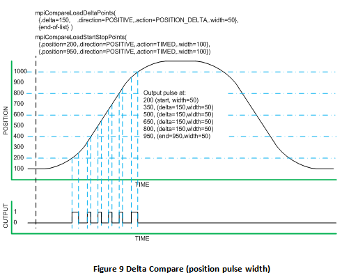
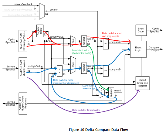
Figure 9 Delta Compare (Position Pulse Width) The data flow for delta compare is shown below. The compare engine initially loads the OutputTimer and start value (into the valueA register) from the Streaming Values dual port RAM. The assert register is also preloaded with the same start value. When the start event triggers, the first output event is triggered, and the first delta value is added to the assert register creating the next compare value. When this first delta value is exceeded, the next delta value is added and so on. When the last delta value is reached, the sequence loops back to the first delta. Meantime, the stop value has been loaded into the valueA register (from the Streaming Values RAM). When the stop event is triggered, the compare engine halts the process. The start and stop values are sent downstream via the cyclic compareEngineDataN packet field. The Delta values are programmed into the Multiple Values RAM via service channel. All of these must be configured prior to enabling the compare engine. Changes are not allowed while the engine is enabled.
Figure 10 Delta Compare Data Flow Programming Delta CompareThe application must configure the FPGA prior to a move using compare:
The application must set the delta (divide-by-N) value sequence, then load start and stop points:
Each ComparePoint defines a 64-bit position, direction, action, and width (time width in ns, or position width in counts). A delta compare point sequence is 1 or more (max 8) compare points, each with a position offset delta, and a position width. The MPI translates each delta point into the necessary service channel commands to configure the FPGA logic. The MPI also translates the Start and Stop point pair into the necessary values to stream through the cyclic data channel to the FPGA. The controller firmware will set the cyclic enable bit (also allowed prior to loading points):
The compare hardware is active and ready to trigger. The application may now command the move. When the initial start position is exceeded, the FPGA hardware will add the first delta offset to calculate the next compare value. This repeats as each value is exceeded, with the hardware calculating each point by adding the next delta offset, until the stop position is exceeded which triggers the final output pulse. The application can append additional start and stop pairs at any time:
The application may monitor eventCount in the status. There is no MPI method for this yet. The controller can provide a compare complete event to the application. There is no MPI support for this event yet. The application cannot modify the delta points until the compare engine has been disabled. The application ends by disabling the compare, and optionally deleting the compare object.
Delta Compare DetailsThis section provides some discusion and advice about specific details of delta compare. Stop Point DetailsThe stop point position deserves extra attention in some applications. Read this following section if your application requires the final pulse to be exactly controlled for example, if precisely 100 output pulses are required. If the application does not need to control the final output pulse, the hardware supports any arbitrary stop position (even if that conflicts with a delta pulse). The compare hardware is simultaneously watching for both the stop point and the next delta point in parallel, so poor choice of stop position might produce inconsistent output pulses (the compare output might behave differently depending on velocity, or update rates, or jitter). The recommended stop point strategy is to set the stop point position to exactly match the next pending delta point position. For example, if the next delta position is at 2200 counts, set the stop pulse to exactly 2200 counts. No matter what happens on the feedback path, the compare logic will always detect the stop point (which takes priority) in the same hardware logic tick that would assert the pending delta pulse. Therefore the stop point attributes will always define the final pulse. Feedback velocity, update rate, or jitter cannot change this result. If the stop point position does not match the final delta point, it may take some analysis to determine the possible interactions of the final delta vs. stop pulses. If the compare output pulses are far apart in time and position, the analysis will be obvious. But the analysis can be complicated if you have time-width pulses, or high velocities, jitter, or large feedback value changes in each logic clock tick (for example AKD-SQ which has a "logical" resolution of 32 bits/rev can have large value changes in adjacent logic clock ticks, so the hardware may detect 2 different position values in the same tick). Direction Bit DetailsThe direction bit is set to 1 for postive motion, or 0 for the reverse direction. This bit controls both the position comparator, and the addition (or subtaction) of the delta offsets. When Direction = 1, the compare engine triggers on [position >= value], and then adds the delta offset (the Pulse Begin register). When Direction = 0, the compare engine triggers on [position<value], and then subtracts the delta offset (the Pulse Begin register). If the application requires pulses in both motion directions, the software would modify the direction bit between the two moves, or else use the directionBoth option. DirectionBoth Bit DetailsIn delta mode only, the MultipleControl registers allow use of a "directionBoth" control bit to override the normal "direction" bit required for all other compare operations. When the directionBoth bit is set, the start point direction will be latched in the hardware, and will control the delta logic until the stop point is reached. The "direction" bit in the MultipleControl register will be ignored when directionBoth is set. The directionBoth feature allows the delta values to be initialized once, then multiple start/stop pairs can be pre-loaded for moves in either direction without any need to modify the delta values. This is good because start/stop pairs can be quickly written into the streaming buffer at any time, including while in motion, where they will be pending until needed (whereas changing delta values uses slow service channel transfers and is not allowed while compare logic is active). Delta Mode Pulse Begin and End DetailsIn the MultipleValues registers, the Pulse Begin value specifies the delta between compare output pulses. This offset is measured from the start (assertion edge) of the prior pulse, to the start (assertion edge) of this pulse, independent of any time-width or position-width values. In the compare hardware engine, the "valueAssert" register is literally only loaded when an output assert occurs. Therefore the actions for position-width, time-width, or assert output all latch the reference point for the next delta position. Special actions such as NOP do not update the register, and do not affect the next delta position calculation. In the MultipleValues registers, the End value specifies the width of the output pulse (assertion edge to negation edge) in position counts or time (depending on the action field). The time-width values are encoded in a 16-bit field (see the section "OutputTimer"). Note the software API stores time values in a different format, then converts to the 16-bit hardware encoding when writing to the FPGA. Delta Mode nextPtr DetailsThe nextPtr bits in the MultipleControl registers control the sequence of delta values. The full flexibility of the nextPtr bits was intended for a different compare mode (Multiple mode). Delta mode always uses very simple sequential nextPtr values, and ignores lastPtr values. The first delta value used after a start point is always Pulse 0. If the nextPtr equals 0 in MultipleControl register 0, this single delta pulse is used every time. To use multiple delta values, set MultipleControl register 0 nextPtr to 1, this tells the compare engine to load Pulse 1 values next. Chain additional pulses by setting each nextPtr value to 2, 3, and so forth until the final pulse sets nextPtr to 0 to complete the sequence. Start and Stop Action Hardware DetailsThe start point must use one of the software actions Position_Width, Timed_Output, or Assert_Output. The stop point must use one of the actions Position_Width, Timed_Output, Assert_Output, or NOP. Other actions are ignored by the start/stop logic. Compare Internal DetailsSome internal details of the compare hardware and software are discussed in this section. Hardware Compare WidthThe FPGA compare hardware width will match the internal feedback counter size for any selected source of any given node. For example, the AKD-SynqNet has a 64-bit internal position, so the compare engine uses a 64-bit comparator. Secondary (Aux) feedback has a 32-bit value (left-justified), so the compare engine uses a 32-bit comparator. The RMB-10V2 has a 32-bit internal feedback position, so the compare engine uses a 32-bit comparator. Any size between 32 bits (minimum) and 64 bits (maximum) is supported via a FPGA compile options. Note MPI software always uses a 64-bit integer position. So for some node types, the MPI has greater position width than the hardware. When the compare hardware is less than 64-bits, the upper position bits are ignored in the hardware comparator. The MPI status for a compare engine includes the width of the selected internal feedback source (and therefore the width of the compare logic). However the MPI does not perform and limit checking on the compare values requested by the application. It is presumed that any reasonable move for a given node will not exceed the range of its internal counters. Therefore it is safe to program any required compare values prior to a move. Further details are below in the rollover discussion. Hardware Compare, Rollover, and Maximum Compare RangeThe compare engine hardware will operate correctly near a rollover value. For example, the feedback position value 0x1 is greater than the compare value of -1, which is represented by the 64-bit value 0xFFFF_FFFF_FFFF_FFFF. The FPGA uses the quadrant compare method to eliminate any rollover issues at any point within the feedback count. Quadrant compare also works at the maximum signed transition, so 0x7FFF_FFFF_FFFF_FFFF is less than 0x8000_0000_0000_0000. Quadrant compare treats the two most significant feedback bits in a special way. The four possible MSbit values are treated as the 4 quadrants of one cycle of the full feedback counter. For any two adjacent quadrants (25% of max feedback apart), we know which is greater than the other. For opposing quadrants (50% of max feedback apart), we can ignore the compare result (eventually they will be adjacent quadrants). For values 75% or more from the current position, the quadrant compare operation will give the wrong result this looks identical to 25% the other direction. From this rule we can determine the maximum compare range for any given node: ½ of the maximum feedback counter value. To preserve safety margin for feedback jitter, the recommended range is ¼ of the maximum feedback range. So for a node with 64-bit feedback, maximum range for any compare value is 2^63, recommended range is 2^62. For 32 bit feedback counter, maximum range for any compare value is 2^31, recommended range is 2^30. Again, the MPI does not police this maximum compare range when loading values into the FPGA. The application must know (or verify) that values are within range of the compare hardware. Since most nodes will have 64-bit hardware, it is unlikely that any real-world system will exceed this range. Maximum Streaming Compare Event RateThe maximum compare rate depends on the packet buffer size and the SynqNet cyclic sample rate. Suggested maximums are shown below.
The peak rate is for any single SynqNet cycle: the number of values in the FPGA's circular buffer matches the packet buffer size, which is therefore the peak rate. Sustained rate is ½ peak rate, since the controller typically requires 2 cycles to reload the packet buffer. Worst-case rate is ¼ of peak rate, to provide additional allowance for MS32 values, and because the compare events will not always align precisely with the SynqNet cycles. The MS32 value is sent at most once per revolution, which limits its impact on maximum rates. Even at high motor speeds, for example 6000 RPM, the MS 32 changes only 100 times per second or once per 40 SynqNet cycles (assuming 4 kHz sample rate). Note a single compare point using "position" width control actually consumes two values (events) in the cyclic packet buffer. A single compare point using "timed" width control consumes only one value (event) unless the time-width is changed, that would require a second value to reload the timer register. MPI Correction for Origin Offset and 1-D/2-D CompensationBy default, the logical position values in MPI compare points are automatically compensated for origin offset. The MPI functions perform this correction at the time compare points are loaded into the controller (in the mpiCompareLoadxxx() methods), based on the axis object origin offset value. Note this is a software correction, not a real-time correction in hardware, so if the origin offset value is changed it may invalidate any compare points already pending in the controller or node. If necessary, the compare compensation mode can be set to use raw hardware values only. The automatic origin correction in the MPI methods will be disabled. The application may still apply its own correction factors. 1-D and 2-D Compensation Tables Not SupportedThe MPI supports both 1D and 2D position compensation tables. The MPI compare methods will not correct for 1D or 2D compensation. This is beyond the scope of the hardware compare engine. The application may still apply its own correction factors. |
||||||||||||||||||||||||||||||||||||||||||
| | | Copyright © 2001-2010 Motion Engineering |