
|
|
| . |
Overview of CompareCompare Features | Compare Modes | Hardware Compare Width | Maximum Streaming Compare Event Rate | The Compare module generates an output signal based on comparison to a position feedback value. When the position exceeds the compare value, the module can generate an output pulse or state (pulse width set by time or position). The compare module is architected for four modes: single-shot compare, streaming compare, multiple compare (sometimes called PLS), and delta compare (similar to divide-by-N). Only streaming mode is completed at this time. The SynqNet compare FPGA logic is controlled by both service channel configuration commands (generated by an application calling MPI methods) and cyclic data (moving streaming compare points from controller memory to the SynqNet node FPGA buffer). 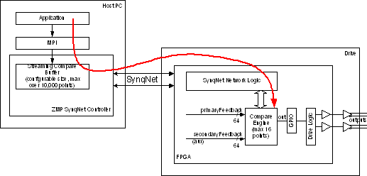 Figure 1 Compare Module System Diagram Note streaming compare allocates a buffer inside the SynqNet controller memory. The application can preload a large number of compare points prior to a move, without any real-time constraints. The controller then updates the packet buffer in each cycle with up to 16 values per cycle, providing a guaranteed update rate. The controller buffer size is set by the application and can exceed 10,000 points (limited only by available controller memory). The packet buffer size determines the maximum event rate. The default is 4 values per packet (typical sustained rate of 2 events per cycle). The application can use custom packet configuration functions to change the packet buffer size, up to a maximum of 16 values. One Compare Module typically contains one Compare Engine, but a compile-time FPGA option allows up to 8 compare engines. Each compare engine has 1 compare output, which connects to an external FPGA pin through the output multiplexer function in the GPIO (general purpose IO) module. The compare engine can select from either the primary or secondary feedback of one motor, and may drive the GPIO outputs for that same motor only (cannot remap outputs to any other axis or node). In addition, time feedback is available for debug and testing. Note the MPI compare software object is independent of the MPI motor object. This preserves the option for a Node IO design with 8 compare outputs per compare module (without requiring a motor). 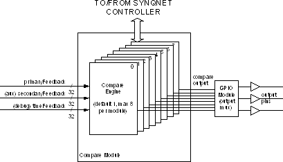 Figure 2 Compare Module Block Diagram The figure below shows the internal data flow used to support the four different modes. Details are provided in each of the following sections. 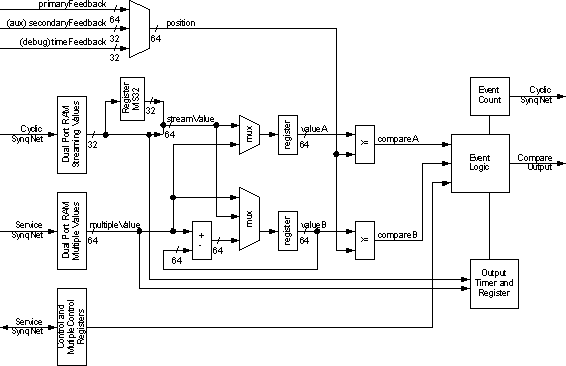 Figure 3 Compare Engine Block Diagram Compare FeaturesKey features of the compare module are listed below.
Compare ModesStreaming compare mode is the only mode available at this time. Streaming Compare Streaming compare provides a sequence of output events. This mode is used for a series of output events during a single move in one direction. The MPI writes a list of compare values (10,000 or more depending on available controller memory). Each value in the list has options for direction (less than or greater than) and output event (timed pulse, asserted, negated, or NOP). Each compare list value generates one output event. As each value is consumed, the next is loaded into hardware. When pulse width is controlled by position, a second value is used to end each pulse. See figures below. When pulse width is controlled by time, the OutputTimer is set via stream (the output timer register is reloaded only when it changes). The MPI is allowed to append additional values while the list is consumed. The MPI can monitor the event count from the FPGA to determine actual events consumed. The MPI can also notify the application for the last event (empty list). By default, the controller sends 4 values per controller cycle to the FPGA using a virtual FIFO. This limits the peak event rate to 4 per controller cycle. Sustained rate is ½ peak since typically 2 cycles are required to reload. Custom packet configuration allows for up to 16 values per packet, which allows a sustained 32,000 events per second assuming 4 kHz sample rate. When pulse width is controlled by position, two compare events per pulse are required. This effectively halves the maximum number of pulses stored in the streaming event list buffer (and halves the maximum event rate). 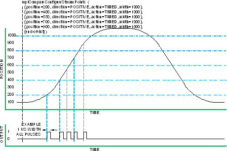 Figure 4 Streaming Compare (timed pulse width) 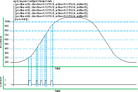 Figure 5 Streaming Compare (position pulse width)  Figure 6 Streaming Compare Append The data flow for streaming compare is shown below. The OutputTimer, MS32, and LS32 values are sent via cyclic SynqNet data through the Streaming Values dual port RAM, creating a 64-bit valueA to compare against the selected position feedback. Up to 16 values can be sent in each SynqNet cycle (each controller sample period), depending on the configured buffer size of the compareEngineDataN packet field. The event logic checks the downstream NextWritePtr field to determine which values in the Streaming Values RAM are valid. The controller monitors the upstream EventCount to determine which values have been detected (and when another new value can be added to the downstream buffer). The cyclic streamMode bits control the action for each value in the stream. Note the OutputTimer and MS32 values are sent only when they change, so at maximum rate only LS32 values are sent (1 compare event per 32-bit word). At the other extreme, if different timed pulse widths are used and the MS32 changes for every event, three 32-bit values are used for each compare event. However MS32 only changes for each motor revolution, which is much slower than the cyclic data rate, so MS32 has little impact.  Figure 7 Streaming Compare Data Flow Programming Streaming Compare The application must configure th FPGA prior to a move using compare:
The application must set the position and action for the compare:
Each ComparePoint defines a 64-bit position, direction, action, and width (time in ns or position counts depending on the action type). The MPI translates this into multiple cyclic commands as necessary to load the MS32 and timer registers. The MPI streams all these points into the controller buffer memory (if the buffer fills, the MPI returns the count of values accepted , the application can later load the remaining points). The controller firmware transfers compare points into the packet buffer (at the controller’s cyclic sample rate), and monitors the cyclic eventCount from the FPGA to ensure each step completes. Additional compare points can be appended with the same method, prior to the move, or during the move:
The controller firmware will set the cyclic enable bit at the start of the move, either by some controller event, or by explicit application command:
The compare hardware is active and ready to trigger. The application may now command the move. The controller firmware transfers compare points into the packet buffer (at the controller’s cyclic sample rate), and monitors the cyclic eventCount from the FPGA to ensure each step completes. The application may monitor eventCount in the status.
The controller can provide a compare complete event to the application (optional interrupt). The application ends by disabling the compare, and optionally deleting the compare object.
Hardware Compare WidthThe FPGA compare hardware width will match the internal feedback counter size for any selected source of any given node. For example, the AKD-SynqNet has a 64-bit internal position, so the compare engine uses a 64-bit comparator. Secondary (Aux) feedback has a 32-bit value (left-justified), so the compare engine uses a 32-bit comparator. The RMB-10V2 has a 32-bit internal feedback position, so the compare engine uses a 32-bit comparator. Any size between 32 bits (minimum) and 64 bits (maximum) is supported via a FPGA compile options. Note MPI software always uses a 64-bit integer position. So for some node types, the MPI has greater position width than the hardware. When the compare hardware is less than 64-bits, the upper position bits are ignored in the hardware comparator. The MPI status for a compare engine includes the width of the selected internal feedback source (and therefore the width of the compare logic). However the MPI does not perform and limit checking on the compare values requested by the application. It is presumed that any reasonable move for a given node will not exceed the range of its internal counters. Therefore it is safe to program any required compare values prior to a move. Further details are below in the “rollover” discussion. Hardware Compare, Rollover, and Maximum Compare Range The compare engine hardware will operate correctly near a rollover value. For example, the feedback position value 0x1 is “greater than” the compare value of -1, which is represented by the 64-bit value 0xFFFF_FFFF_FFFF_FFFF. The FPGA uses the “quadrant compare” method to eliminate any rollover issues at any point within the feedback count. Quadrant compare also works at the maximum “signed” transition, so 0x7FFF_FFFF_FFFF_FFFF is less than 0x8000_0000_0000_0000. Quadrant compare treats the two most significant feedback bits in a special way. The four possible MSbit values are treated as the 4 quadrants of one cycle of the full feedback counter. For any two adjacent quadrants (25% of max feedback apart), we know which is greater than the other. For opposing quadrants (50% of max feedback apart), we can ignore the compare result (eventually they will be adjacent quadrants). For values 75% or more from the current position, the quadrant compare operation will give the wrong result – this looks identical to 25% the other direction. From this rule we can determine the maximum compare range for any given node: ½ of the maximum feedback counter value. To preserve safety margin for feedback jitter, the recommended range is ¼ of the maximum feedback range. So for a node with 64-bit feedback, maximum range for any compare value is 2^63, recommended range is 2^62. For 32 bit feedback counter, maximum range for any compare value is 2^31, recommended range is 2^30. Again, the MPI does not police this maximum compare range when loading values into the FPGA. The application must know (or verify) that values are within range of the compare hardware. Since most nodes will have 64-bit hardware, it is unlikely that any real-world system will exceed this range. Maximum Streaming Compare Event RateThe maximum compare rate depends on the packet buffer size and the SynqNet cyclic sample rate. Suggested maximums are shown below.
Note a single compare point using “position” width control actually consumes two values (events) in the cyclic packet buffer. A single compare point using “timed” width control consumes only one value (event) – unless the time-width is changed, that would require a second value to reload the timer register. The peak rate is for any single SynqNet cycle: the number of values in the FPGA buffer matches the packet buffer size, which is therefore the peak rate. Sustained rate is ½ to ¼ of peak rate, since the controller typically requires 2 cycles to reload the packet buffer, some allowance for MS32 values is required, and the compare events will not always align precisely with the SynqNet cycles. The MS32 value is sent at most once per revolution, which limits its impact on maximum rates. Even at high motor speeds, for example 6000 RPM, the MS 32 changes only 100 times per second or once per 40 SynqNet cycles (assuming 4 kHz sample rate). MPI Correction for Origin Offset and CompensationSince the hardware compare engine uses raw feedback values, the application must deal with correction for origin offset and compensation tables. MPI application programmers typically work with “actual position” values, which differ from the raw feedback values in two ways:
|
||||||||||||||||||||||||||
| | | Copyright © 2001-2021 Motion Engineering |