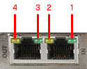
SynqNet controller LEDs will BLINK to indicate a fault
(or undiscovered network). A controller with no blinking LEDs is in normal
cyclic operation (without faults). Each SynqNet port has two LEDs. And
each LED has a particular function, which is described in further detail
below.
LED |
Port |
Meaning |
Controlled by |
State |
LED1 |
OUT
|
Link Activity
|
PHY
|
ON = link active
|
OFF = link inactive
|
LED2 |
OUT
|
Network Activity
|
MAC
|
ON = Tx and Rx active
(cyclic phase)
|
BLINK = Tx only active
(discovery phase)
|
OFF = Idle (shutdown phase), or during
a network reset.
|
LED3 |
IN
|
Link Activity
|
PHY
|
ON = link active
|
OFF = link inactive
|
ON = Tx
|
LED4 |
IN |
Network
Activity |
MAC |
ON = Tx and Rx active
(cyclic phase)
|
BLINK = Tx only active
(discovery phase)
|
OFF = idle (shutdown phase), or during
a network reset.
|