.

TSIO-4008; Digital Output

16 Channels of 24Vdc/0.3A Sourcing Output

  • The module has 16 Channels of source type output for 24Vdc/0.3A.

  • The connected load is switched via the digital output from the control system.

  • All outputs are electronically over-current protected.

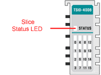
  • The module has 17 status LEDs.
    (1- network status, 16- field device status)

  • Each output is electrically isolated from the controller by the use of a photocoupler.


Output Specification
Outputs per module 16 channels non-isolated, source type
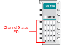
LED Indicators 16 green for output status
1 green/red for slice status
ON-state Voltage Range 24Vdc nominal
11 ~ 28.8Vdc
ON-state Voltage Drop Max. 0.5Vdc
ON-state Current Min. 1mA / channel
OFF-state Leakage Current Max. 50uA
Output Signal Delay OFF to ON: 1ms Max.
ON to OFF: 1ms Max.
Output Current Rating Max. 0.3A per output,
Max. 4.0A per common
Protection Over Current Protection: Electrical Fuse 125Vdc/6.3A

General Specification
ID 0x00160181
Logic Power Dissipation Max. 45mA @ 5.0Vdc
Isolation I/O to Logic: Photocoupler isolation
Isolation Voltage: 1250Vrms/Vac
Field Power: No isolation
Field Power
(Internal Power Bus)
Supply Voltage: 24Vdc nominal
Voltage Range: 11 ~ 28.8Vdc
Power Dissipation: 5mA @ 28.8Vdc / channel
I/O Cables Max. AWG 14
Weight 70g
Module Size 99mm x 12mm x 70mm
(H x W x L)
Environmental Requirements See Environment Requirements


Pinouts

Pin No.
Description
1
Output Channel 0
2
Output Channel 1
3
Output Channel 2
4
Output Channel 3
5
Output Channel 4
6
Output Channel 5
7
Output Channel 6
8
Output Channel 7
9
Output Channel 8
10
Output Channel 9
 
Pin No.
Description
11
Output Channel 10
12
Output Channel 11
13
Output Channel 12
14
Output Channel 13
15
Output Channel 14
16
Output Channel 15
17
Field Ground (0V)
18
Field Ground (0V)
19
Field Power (+24V)
20
Field Power (+24V)


Parameters

Parameter
Access
Bits
Description
Default
0
Read
and
Write
0-7
Fault Action (channels 0 to 7)
0: Fault Value (see parameter 2)
1: Hold Last State
0
(Fault Value)
1
Read
and
Write
0-7
Fault Action (channels 8 to 15)
0: Fault Value (see parameter 3)
1: Hold Last State
0
(Fault Value)
2
Read
and
Write
0-7
Fault Value (channels 0 to 7)
0: OFF
1: ON
0
(OFF)
3
Read
and
Write
0-7
Fault Value (channels 8 to 15)
0: OFF
1: ON
0
(OFF)

See Also: Slice Parameters


Memory

This slice does not support any memory registers.


I/O Data

 
Output Data
Bit No.
Bit 7
Bit 6
Bit 5
Bit 4
Bit 3
Bit 2
Bit 1
Bit 0
Byte 0
CH7
CH6
CH5
CH4
CH3
CH2
CH1
CH0
Byte 1
CH15
CH14
CH13
CH12
CH11
CH10
CH9
CH8


Slice Status LED

State
LED
Description
Not Powered,
Not Initialized
OFF The slice is either not powered or has not been initialized.
Normal Communication Green
Slice to network adapter communication is operating normally.
Communication Ready Flashing Green Slice to network adapter communication is ready to be started.
Communication Fault Flashing Red

Slice to network adapter communication has a fault.

Slice Fault Red

The slice has a fault.


Channel Status LED

The TSIO-4008 has 16 Channels.

State
LED
Indicates
Signal OFF OFF Normal Operation (Active)
Signal ON Green
Normal Operation (Inactive)


       Legal Notice  |  Tech Email  |  Feedback
      
Copyright ©
2001-2021 Motion Engineering