TSIO-2009; Digital Input
16 Channels of 12V/24Vdc Sinking Input
|
|
- The module has 16 Channels of sink type input. It receives
signals with values of 12Vdc/24Vdc.
- The digital input module receives the control signal from digital
field devices. (sensor, etc)
- The module has 17 status LEDs.
(1- network status, 16- field device status)
- A photocoupler is used for electrical isolation between the
controller and external field connections.
- The module has 2 wires. A 3-wire sensor (proximity, etc) can
also be connected.
|
| Input Specification
|
| Inputs per module |
16 channels of non-isolated, sink
type |
| LED Indicators |
16 green for input status
1 green/red for slice status |
| ON-state Voltage Range |
24Vdc nominal
11 ~ 28.8Vdc |
| OFF-state Voltage Range |
0Vdc nominal
-3 ~ 5Vdc |
| ON-state Current |
Max. 6mA /channel @ 28.8Vdc |
| Input Signal Delay |
OFF to ON: 3ms Max.
ON to OFF: 3ms Max. |
| Filtering Time |
Typ. 1.5ms |
| General Specification |
| ID |
0x00130141 |
| Logic Power Dissipation |
Max. 45mA @ 5.0Vdc |
| Isolation |
I/O to Logic: Photocoupler isolation
Isolation Voltage: 1250Vrms/Vac
Field Power: No isolation
|
Field Power
(Internal Power Bus) |
Supply Voltage: 24Vdc nominal
Voltage Range: 11 ~ 28.8Vdc
Power Dissipation: 5mA @ 28.8Vdc / channel
|
| I/O Cables |
Max. AWG 14 |
| Weight |
65g |
| Module Size |
99mm x 12mm x 70mm
(H x W x L) |
| Environmental Requirements |
See Environment
Requirements |
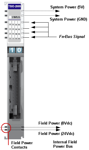
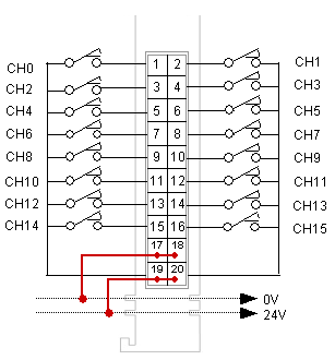
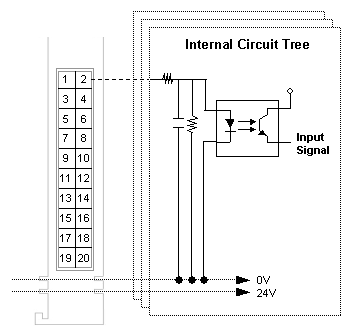
Pinouts
|
|
|
Pin No.
|
Description
|
|
1
|
Input Channel 0 |
|
2
|
Input Channel 1 |
|
3
|
Input Channel 2 |
|
4
|
Input Channel 3 |
|
5
|
Input Channel 4 |
|
6
|
Input Channel 5 |
|
7
|
Input Channel 6 |
|
8
|
Input Channel 7 |
|
9
|
Input Channel 8 |
|
10
|
Input Channel 9 |
|
|
|
Pin No.
|
Description
|
|
11
|
Input Channel 10 |
|
12
|
Input Channel 11 |
|
13
|
Input Channel 12 |
|
14
|
Input Channel 13 |
|
15
|
Input Channel 14 |
|
16
|
Input Channel 15 |
|
17
|
Field Ground (0V) |
|
18
|
Field Ground (0V) |
|
19
|
Field Power (+24V) |
|
20
|
Field Power (+24V) |
|
|
Parameters
This slice does not support any parameters.
See Also: Slice Parameters
Memory
This slice does not support any memory registers.
See Also: Slice Memory
I/O Data
| |
Input Data |
Bit No. |
Bit 7 |
Bit 6 |
Bit 5 |
Bit 4 |
Bit 3 |
Bit 2 |
Bit 1 |
Bit 0 |
Byte 0 |
CH7 |
CH6 |
CH5 |
CH4 |
CH3 |
CH2 |
CH1 |
CH0 |
Byte 1 |
CH15 |
CH14 |
CH13 |
CH12 |
CH11 |
CH10 |
CH9 |
CH8 |
|
Slice Status LED
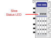
State |
LED |
Description |
Not Powered,
Not Initialized |
OFF |
The slice is either not powered or has not been initialized. |
| Normal Communication |
Green
|
Slice to network adapter communication is operating normally. |
| Communication Ready |
Flashing Green |
Slice to network adapter communication is ready to be started. |
| Communication Fault |
Flashing Red |
Slice to network adapter communication has a fault. |
| Slice Fault |
Red |
The slice has a fault. |
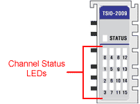
Channel Status LED
The TSIO-2009 has 16 Channels.
|
State
|
LED
|
Indicates
|
| Signal OFF |
OFF |
Normal Operation (Active) |
| Signal ON |
Green
|
Normal Operation (Inactive) |
|


