|
|
| . |
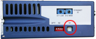
S200: Switch SettingsThe configuration switches S1 and S2 are located on the top of the drive. Although the drive can be configured to not use the switches, the factory default configuration uses the switches for selecting Torque/Current versus Velocity operational mode, SFD or 6-step feedback device, and emulated encoder line count. S1: Rotary Setup Switch; SFD FeedbackS1 is a 10-position rotary switch. The function of S1 depends on the feedback mode in which the drive is configured. NOTE: The emulated encoder output is only available when using SFD feedback to the base unit or when a high-resolution feedback device is connected to the option card.
1 - S1 position 0 allows setting the non-volatile line count via the drive parameter EncOut to any of the following values: 128, 512, 1024, 2048, 4096, 8192, 16384, 32768125, 500, 1000, 2000, 2500, 5000, 10000, 20000 The value that is written replaces the factory default value listed in position 0 of the table. S1 Function with SFD FeedbackWhen using the Smart Feedback Device (SFD), S1 sets the emulated encoder line count.
1 - The S1 position 0 allows setting the non-volatile line count via the drive parameter EncOut to any of the following values: 128, 512, 1024, 2048, 4096, 8192, 16384, 32768125, 500, 1000, 2000, 2500, 5000, 10000, 20000. The value written replaces the factory default value listed in position 0 of the table. NOTE: The emulated encoder output is only available when using SFD feedback to the base unit or a high-resolution feedback device connected to the option card. S1 Function with 6-Step FeedbackIn 6-step mode, S1 sets the current loop proportional gain, KIP. Set S1 to the value listed in the table for your drive type and motor inductance. Consult the factory if the motor inductance is lower or higher than what can be accommodated by S1. An incorrect setting of KIP can cause current loop instability or oscillation potentially resulting in damage to the drive or application. Motor Inductance Tables for 6-step Commutation (L in mH)
2 - The S1 position 0 allows the setting of non-volatile KIP via the serial port to any valid value in 6-Step mode. The value written will replace the default value listed in position 0 of the table.
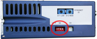
S2 : DIP Setup Switch; Type SettingS2 is a 4-position dip switch. Switch positions 1 and 2 can set the operational mode and feedback types when enabled. Setting the drive parameters as shown in the following table enables the switch and is the factory default configuration. Switch positions 3 and 4 are reserved for future functionality and should be left in the down/closed factory default position.
NOTE: Drive parameter settings can override the S2 switch settings. To enable S2 for setup verify that the following drive parameters are set as shown below. The factory default is to ship the drive with the switches enabled:
|
|||||||||||||||||||||||||||||||||||||||||||||||||||||||||||||||||||||||||||||||||||||||||||||||||||||||||||||||||||||||||||||||||||||||||||||||||||||||||||||||||||||||
| | | Copyright © 2001-2021 Motion Engineering |