|
|
| . |
Quick Start Guide:
|
||||||||||||||||||||||||||||||
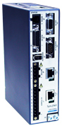 S200 SynqNet Drive |
 S200 Tools |
This Quick Start Guide is designed to help a user quickly setup one of the following S200 Drives. See Drive Names and Descriptions for a complete list of S200 drives.
|
The setup consists of the following steps:
Before you can use an S200-SynqNet Drive, you must first install the Motion Developer's Kit Software package and SynqNet controller from Motion Engineering Inc. For more information about installation, please see MEI's Technical Support website.
For installation instructions, see S200 Tools Software Installation Guide.
S200 Tools supports the following Operating Systems:
|
NOTE: The drive serial port (J5) is disabled on SynqNet drives.
If you are using an S200 SynqNet Drive, you need to establish SynqNet communication link between the S200 SynqNet Drive and the SynqNet motion controller.
|
Depending on the type of motor feedback that is used, you will need to use the appropriate feedback connector.
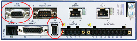
Motor Feedback |
J3 FEEDBACK |
J14 AUX FB |
| SFD | X |
- |
| SinCos (with Endat 2.1) | - |
X |
| SinCos (with Halls) | - |
X |
| ComCoder (Incremental + Halls) | - |
X |
Launch the S200 Tools program by clicking the desktop icon or from the Windows Start button (Programs > Danaher Motion > S200Tools). The default location for S200Tools.exe, is
(C:\Program Files\Danaher Motion\S200Tools).
![]()
When the S200 Tools program is launched for the first time, no drives should be listed under the Online or Offline Communications Mode.
Open the Communication Wizard by selecting it from the toolbar (Utilities > Communication Wizard) or clicking the shortcut icon.
Select SynqNet as the Communications Mode.
If you do not know which type of drive is connected, click the Test button. The returned message will either say that there is no connection, confirm that you have an S200 connected, or tell you that the connected node is NOT an S200 drive.
Troubleshooting If you receive the "No Connection" message, check the hardware connections. |
After you have confirmed your setup, click the OK button.
The installed S200 drive(s) will now be listed as "Online" and will list its configuration and status options. If there are additional S200 nodes on the network, they are automatically discovered. When using a network with multiple SynqNet nodes, use the SynqNet controller/node pulldown bars to select a particular node on the network to display in the Online mode.
NOTE for SynqNet: Although the S200 Tools software maintains communication with all properly connected S200 drives drives on the SynqNet network, only one SynqNet node will be displayed at a time under the Online display.
The next step is to set the proper drive and motor feedback configurations.
Under the SynqNet Options tab, select the source for motor feedback (Feedback Source).
Select Base Unit Feedback if the motor feedback is connected to J3 on the S200 Drive.
Select Option Card Feedback if the motor feedback is connected to J14 on the S200 Drive.
The next step is to set the proper motor feedback configurations.
If you are using SFD motor feedback, no further configuration is needed.
If you are using SinCos or ComCoder as motor feedback, use the equations below to determine the appropriate parameters for setup.
Kip = 2*Π()*2000*(motor line to line inductance)
Ex:
l-l inductance = 0.018 H
Kip = 2*PI()*2000*(0.018)
Kip = 226 V/A
I2TF0 = 5/[(2Π)*(motor time constant in minutes)*60]
Ex: Mtc = 20 minutes
I2TF0 = 5/(2*PI()*20*60)
I2TF0 = 0..000663 Hz
I2TTrip = (motor continuious current)*1.25
Ex: Ics = 4 ARMS
I2TTrip = 4*1.25
I2TTrip = 5 ARMS
ILmtPlus = (motor peak current)/(drive peak current)*100
Ex: Motor Ip = 4.5 ARMS, Drive Ip = 9 ARMS
Motor Ip = (4.5/9)*100
Motor Ip = 50%
Typically ILmtMinus is set to the same value as ILmtMPlus. Although there can be asymetrical current limits in the drive.
Dpoles = motor poles
There are three types of Save options. It is important to know how to use each type to ensure that configurations are not lost.
|
| | | Copyright © 2001-2021 Motion Engineering |