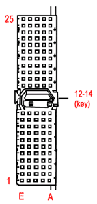
DSP-CPCI: Rear I/O Bus J4
| |
 |
For Header Locations:
|
|
Pin
|
E
|
D
|
C
|
B
|
A
|
|
25
|
+5V |
Encoder Index(4)– |
Encoder Index(4)+ |
Encoder Index(3)– |
Encoder Index(3)+ |
|
24
|
Gnd |
Encoder B(4)– |
Encoder B(4)+ |
Encoder A(4)– |
Encoder A(4)+ |
|
23
|
Encoder Index(5)+ |
Encoder B(5)– |
Encoder B(5)+ |
Encoder A(5)– |
Encoder A(5)+ |
|
22
|
Encoder Index(5)– |
Encoder B(6)– |
Encoder B(6)+ |
Encoder A(6))– |
Encoder A(6)+ |
|
21
|
Reserved |
Encoder B(7)– |
Encoder B(7)+ |
Encoder A(7)– |
Encoder A(7)+ |
|
20
|
Reserved |
Encoder Index(7)– |
Encoder Index(7)+ |
Encoder Index(6)– |
Encoder Index(6)+ |
|
19
|
Negative Limit(0) |
Positive Limit(0) |
Home Input(0) |
Amp Fault(0) |
Amp Enable(0) |
|
18
|
Reserved |
In Position(1) |
User I/O PC0 |
Reserved |
In Position(0) |
|
17
|
Negative Limit(1) |
Positive Limit(1) |
Home Input(1) |
Amp Fault(1) |
Amp Enable(1) |
|
16
|
Negative Limit(2) |
Positive Limit(2) |
Home Input(2) |
Amp Fault(2) |
Amp Enable(2) |
|
15
|
Reserved |
In Position(3) |
User I/O PCI |
Reserved |
In Position(2) |
|
14
|
Key Area |
Key Area |
Key Area |
Key Area |
Key Area |
|
13
|
|
12
|
|
11
|
Negative Limit(3) |
Positive Limit(3) |
Home Input(3) |
Amp Fault(3) |
Amp Enable(3) |
|
10
|
Negative Limit(4) |
Positive Limit(4) |
Home Input(5) |
Amp Fault(4) |
Amp Enable(4) |
|
9
|
Reserved |
In Position(5) |
User I/O PC2 |
Reserved |
In Position(4) |
|
8
|
Negative Limit(5) |
Positive Limit(5) |
Home Input(5) |
Amp Fault(5) |
Amp Enable(5) |
|
7
|
Negative Limit(6) |
Positive Limit(6) |
Home Input(6) |
Amp Fault(6) |
Amp Enable(6) |
|
6
|
Reserved |
In Position(7) |
User I/O PC3 |
Reserved |
In Position(6) |
|
5
|
Negative Limit(7) |
Positive Limit(7) |
Home Input(7) |
Amp Fault(7) |
Amp Enable(7) |
|
4
|
User I/O PC4 |
User I/O PA3 |
User I/O PA2 |
User I/O PA1 |
User I/O PA0 |
|
3
|
User I/O PC5 |
User I/O PA7 |
User I/O PA6 |
User I/O PA5 |
User I/O PA4 |
|
2
|
User I/O PC6 or DSP Interrupt |
User I/O PB3 |
User I/O PB2 |
User I/O PB1 |
User I/O PB0 |
|
1
|
User I/O PC7 or PC Interrupt |
User I/O PB7 |
User I/O PB6 |
User I/O PB5 |
User I/O PB4 |
|
Pin
|
E
|
D
|
C
|
B
|
A
|
|
