|
|
| . |
SIM4 Option: Installation and Calibration
IntroductionIf your XMP application requires increased position resolution and your scale has sinusoidal outputs, you can use the SIM4 (scale interpolation module) with the XMP. The SIM4 module is available with three configurations:
Variations
About Scale Interpolation IMPORTANT: When enabling the SIM4, adjust filter parameters and limits to allow for encoder count rates 1024 times larger than non-interpolated count rates. SIM4 ArchitectureXMP Architecture for 8 Motors
XMP Architecture for 16 Motors
SIM4 Block DiagramConnections to the SIM4 module are made through the standard input connectors. The COS (cosine) signals are connected to ENCA (encoder A) inputs, the SIN (sine) signals to the ENCB (encoder B) inputs, and the encoder index signals to the ENCI (encoder index) inputs. Motors are set up individually in interpolated or non-interpolated mode through the MPI. Capture and Compare are handled in the same way for interpolated as for noninterpolated configurations.
For encoders with sinusoidal outputs, the scale interpolation module provides increased position resolution for up to 4 motors per SIM4. These outputs produce one cycle of sine and cosine analog signals for each scale line pair. At every sample, the scale interpolation module reads the sine and cosine levels and determines the angular position within the encoder’s line pair. The sine and cosine outputs are also routed to the standard quadrature inputs, providing coarse position information. The quadrature inputs generate 4 counts for every line pair, while the 12-bit interpolated value generates 4096 counts for each line pair. The full interpolated position is obtained by combining the number of quadrant counts divided by 4, with the position between two encoder lines. The 12-bit scale interpolation provides a resolution increase of 1024 over the quadrature counters. To maintain accurate phase information, the sine and cosine signals are captured with simultaneous-sampling A/D converters. Position CompareTo implement the position compare feature, the SIM4 compares the current position to a position latched in the FPGA. The A/D converters convert continuously, with a 10 µsec latency.
Maximum Count RateThe maximum count rate of the SIM4 is determined by the rolloff of the analog input stage of the SIM4. The 3db point is at 200kHz. The SIM4 will operate at higher frequencies, but since the signal will be attenuated more at higher frequencies, the signal-to-noise ratio will go down. The highest frequency of operation will depend on possible DC offsets in the raw signals. Running the SIM4 at sin/cos frequencies above 200kHz is NOT recommended. Since each cycle produces 4096 counts, the recommended effective upper count rate is 120,000 * 4096 counts/sec. Position CaptureTo implement the position capture feature, the SIM4 latches the full interpolated position when the user-supplied latch signal is pulsed. Note that different motors can be latched independently of each other.
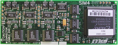
SIM4 Hardware InstallationThe SIM4 module is a mezzanine-style module designed to plug directly into the XMP-Analog control card; up to two SIM4 modules may be installed per board. A simple procedure is used to install a module. NOTE: For steps #2-5 below, observe all electrostatic discharge (ESD) precautions, including use of a grounded ESD wristband and component mat. Failure to observe ESD precautions may result in damage to the SIM4 module and/or the XMP-Analog controller.
SIM4 ConfigurationTo operate the XMP with scale interpolation, the SIM4 module is installed onto the XMP-Analog controller (see SIM4 Hardware Installation), and the XMP-Analog controller is configured for scale interpolation. Configuring the XMP-Analog controller for SIM4 operation is illustrated in the Sim4.c sample application. The XMP-Analog can also be set up for SIM4 operation through Motion Console, by toggling the SIM4 button in the Motor Summary / Config tab. After executing Sim4.c, the XMP-Analog returns position measurements with a resolution of 1024 times the quadrature resolution. The limits and filter parameters must therefore be adjusted to correspond to the higher count rate. Once these steps are taken, the XMP-Analog is ready to operate in interpolated mode. In interpolated mode, the Xmp/SIM4 determines the angular position at a given time by sampling the sine and cosine signals simultaneously, and looking up the angle in the arctan lookup table, located in the SIM4 flash. Ideally, the sine and cosine signals should have no DC offsets and should have equal amplitudes. If there are DC offsets and amplitude differences, the angle obtained from the lookup table based on the raw values will be incorrect. Under these conditions, increased accuracy is obtained by calibrating the sinusoidal scale and compensating the sine and cosine values before looking up the angle in the arctan lookup table as described below. Compensation is illustrated in the series of figures below. Figure 8a shows the ideal sine/cosine relationship. Figure 8b shows the case where the cosine amplitude is larger than the sine amplitude, and where both sine and cosine have a DC offset. Figure 8c shows the sine and cosine after compensation.
The first part of the calibration process for a given motor consists of measuring the DC offsets and the amplitude differences, then computing a set of compensation lookup tables. This is done with Sim4Cal.c. This application moves the scale over a short distance in the region of operation and determines the maximum and minimum of each signal. One sine/cosine sample is collected every servo cycle. The move distance should be long enough to encompass several cycles of the encoder signals, and the velocity of the move should be low enough to sample at least 50 points per sine or cosine cycle. The compensation tables for sine and cosine are stored in an output file. The second part of the calibration consists of loading the compensation tables into the flash on the sim4 module. This is done with Sim4Flsh.c. The contents of the SIM4 flash are non-volatile. They will remain unchanged through resets and power-downs. A compensation table can be replaced by an improved one or by a unity-transfer-function table by a new execution of Sim4Flsh.exe with the appropriate arguments. The unity-transfer-function compensation table is generated by running Sim4Cal with the “nocal” argument. If desired, the relevant sections of Sim4Cal.c and Sim4Flsh.c can be combined within the user’s application code to perform scale calibration in-line. The details of the programs follow. Sample ApplicationsThe sample application programs below can be used to configure and calibrate your SIM4 module. All of them are found in the software tree shipped with your hardware. Sim4.c Sim4Cal.c Sim4Flsh.c Sim4.cThis sample application configures a motor for SIM4 operation and for capture on the Encoder Index ANDed with ENCA and ENCB. Sim4Cal.cThis sample application computes the compensation tables for a SIM4 motor and
saves the data in a file.
The program assumes that the PID parameters, error limits, and velocity tolerances
are set up prior to running this application. The program sets the relevant motor up
Sim4Cal without any arguments generates the compensation tables for sine and cosine for motor 0 in the file cal.abs. An ascii version of the data is stored in cal.txt. The raw values collected for sine and cosine are stored in output.txt. Sim4Cal -file <filename> generates the compensation tables for motor 0 and stores the data in files: filename.abs, filename.txt, and output.txt. Sim4Cal cal -motor # -file <filename> generates the compensation tables for motor # and stores the data in files: filename.abs, filename.txt, and output.txt. Sim4Cal nocal generates unity transfer sine and cosine compensation lookup tables (i.e. tables applicable for zero DC offsets and equal amplitude for sine and cosine) and stores the data in files: cal.abs, cal.txt, and output.txt. Sim4Flsh.cThis application loads the SIM4 flash with the arctan table and the sine and cosine compensation tables. SIM4 uses the compensation tables to correct analog sine and cosine inputs for DC offsets and for amplitude differences between the two signals. It then uses the arctan lookup table to obtain the interpolated position value from the corrected sine and cosine inputs. MEI distributes a default configuration of the flash (sim4.abs). The compensation tables in the default configuration are unity transfer compensation tables for all motors. The SIM4 flash file is partitioned into areas for the arctan lookup table and the sine and cosine compensation tables. There is a sine and cosine compensation table for each motor. Sim4flsh can load the entire SIM4 flash area or a compensation table for a single motor. When Sim4Flsh is invoked without arguments, it expects to load the entire flash area with a file named sim4.abs on Motion Block 0. To flash another MotionBlock, the –block argument is used. A different filename can be specified with the –file option. A compensation table for a specific motor can be loaded with the cal and -motor arguments. Compensation tables can be created with the sim4cal program. To create a file for the entire flash area, generate the necessary individual compensation tables with the sim4cal program and load them into flash. Then use “sim4flsh get –block #” to write the entire flash area into a file. The default filename is sim4.abs. Do NOT to overwrite the default configuration distributed by MEI. Command line arguments:
NOTE: -motor and -block are mutually exclusive. Examples sim4flsh sim4flsh -block # sim4flsh cal -motor # -file <filename> sim4flsh get sim4flsh get –block # -file <filename>
|
||||||||||||||||||||||||||||||||||
| | | Copyright © 2001-2021 Motion Engineering |