Drive Enable Wiring
Definition of Fail Safe Wiring
One of the first questions motion system designers must address is how
to wire the AmpEnable to a drive for fail safe operation. A fail safe
drive enable circuit is one that is disabled when either the controller
loses power or control lines are cut. MEI strongly recommends avoiding
any configuration where loss of power leads to a runaway axis. In many
cases, the use of automatic, dynamic braking is recommended for high-mass,
high-speed loads.
Wiring and Drive Behavior
The actual behavior of a drive enable circuit depends upon two factors:
| |
- The drive's internal configuration.
- How the Amp Enable line is wired between the XMP controller
and the drive.
|
Two examples of fail safe wiring are shown below. They
do not represent the only correct way to configure drives, but they can
be used as guides.
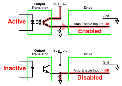
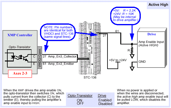
Example 1: Active High
In the case of an active high drive enable input, the
drive is "enabled" when the Amp Enable signal is high. The diagram below
shows how to connect a fail-safe circuit. Normally, the controller's output
transistor is inactive. When the transistor is inactive (OFF), the resistor
pulls Amp Enable Input to ground, disabling the drive. When the transistor
is active (ON), the Amp Enable Input is pulled up to +5V or +24V, enabling
the drive.
Active high wiring.
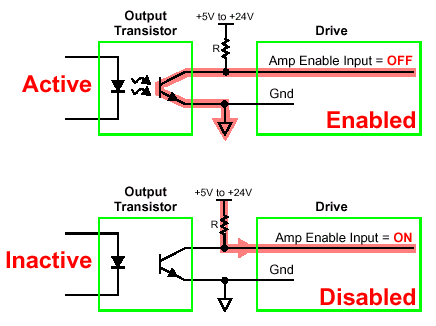
Example 2: Active Low
In the case of an active low drive enable input, the
drive is "enabled" when the Amp Enable signal is low. The diagram below
shows how to connect a fail-safe circuit. Normally, the controller's output
transistor is inactive. When the transistor is inactive (OFF), the resistor
pulls the Amp Enable Input up to +5V or +24V, disabling the drive. When
the transistor is active (ON), the Amp Enable Input is pulled to ground,
enabling the drive.
Active low wiring.
Setting Amp Enable and Polarity
from Motion Console
When operating drive amplifiers with Motion Console, you must indicate
the following:
| |
- the state of the amplifier: Enabled or Disabled (unchecked)
- the polarity of the amplifier: Inverted or Normal (unchecked)
|
This is done using the Amp Enable and Amp Polarity
parameters within the Motor Summary / Config tab page:
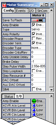
The Amp Enable parameter is for use with drives equipped
with enable lines. On such drives, the amplifier responds to commands
only when the Amp Enable parameter is set to Enabled. If Amp Enable is
not enabled, the amplifier will not respond to commands. For fail-safe
operation, the Amp Enable logic is determined by the wiring between the
controller and drive. In this case, the Amp Polarity should be set to
Inverted. The Amp Polarity parameter tells the XMP controller whether
the output transistor should be normally inactive, to disable the drive
(Inverted) or normally active, to disable the drive (Normal). Only the
"Inverted" Amp Polarity setting supports fail-safe wiring, and is strongly
recommended.
Amp Enable Output
The optically-isolated Amp_Enable outputs provide control
of the servo amplifier, allowing the XMP to disable the amplifier under
fault conditions.
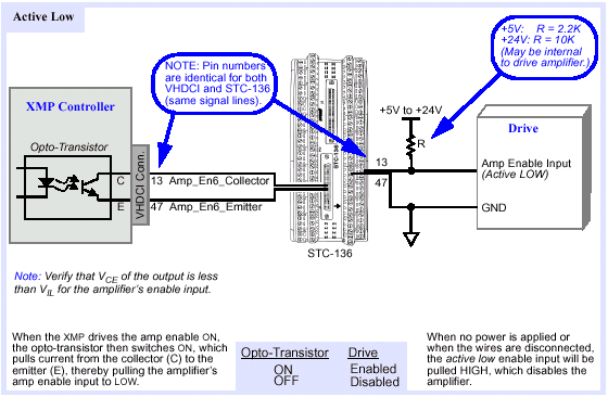
Active LOW Drive Enable Wiring
Connect Amp Enable output to
drive (active LOW).
Active HIGH Drive Enable Wiring
Connect Amp Enable output to
drive (+5/24V, active HIGH).
Amplifier Enabling from the
MPI
Amplifier enabling is a crucial safety issue in the design of your application.
Your system should be designed to anticipate the possibility of a sudden
loss of power and/or connectivity to the controller and/or drive.

To make a full accounting of your motion system's safety
features, you must also address the system's mecahnical dynamics with
a disabled drive. (A disabled drive does NOT necessarily mean that all
motion will be stopped!) In many cases, the use of automatic, dynamic
braking is recommended for high-mass, high-speed loads. Determining whether
an amplifier remains enabled or disabled with the controller powered OFF
depends upon several factors:
| |
- Does the drive have an Amp Enable line? (Not all drives
do. Check this!) Is the drive's Amp Enable line internally configured
as active-high or active low?
- How is the Amp Enable line wired between the controller and
the drive? With power OFF to the controller, does wiring pull
the drive's Amp Enable line HIGH or LOW?
- How is the Amp Enable line configured on the controller when
it is powered? Is the Amp Enable output transceiver normally ON
or OFF? Is the Amp Enable output inverted?
- Does the application software maintain the Amp Enable line in
an enabled state when running? Is the controller's position error
limit configured for Abort (disables the drive)? Does the application
respond to states, disabling or enabling the drive?
|
State logic for active high and active
low drives
|
DRIVE
|
WIRING
|
STATE
|
|
How is the drive's Amp Enable line internally
configured?
|
With power to the controller OFF, current
to the drive's Amp Enable line is...
|
When power to the controller is OFF, the drive
is...
|
|
Active High
|
High
|
Enabled
|
|
Low
|
Disabled*
|
|
Active Low
|
High
|
Disabled*
|
|
Low
|
Enabled
|
|
* Recommended configuration.
|
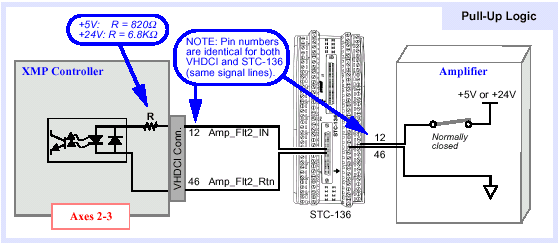
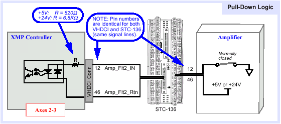
Amp Fault Input
To Pull-up Logic
Connect Amp Fault input to
amplifier (pull-up logic).
To Pull-down Logic
Connect Amp Fault input to
amplifier (pull-down logic).
Previous | Next
|

