
|
|
| . |
PID Tuning:
|
||||
When using this tuning method, be sure that the command output (DAC) is not clipping the step command. If the command output does clip the step command, you have a non-linear system. If the system is non-linear, the generalizations made on this page may not apply. If you are determined to tune despite the non-linearities, make sure that there is a repeatable way to generate the non-linearities, as well as the ability to try many different scenarios.
Kd: With Kp, Ki, Kpff, Kaff, Kvff, and Kfff all set to zero, command a small motion. You are going to make your step command with this motion, so choose an appropriate length. (Small moves are usually best.) In any case, do not clip the command output (DAC) severely, as that will make the result less representative of a normal move.
Use an extremely large acceleration, deceleration, and velocity (1e10 counts / sec2 should be enough for most systems -- make sure the commanded position makes a sharp step as seen in Motion Scope) to make the commanded motion a step. The key to making a step response on the XMP is to turn the acceleration, deceleration, and velocity up high enough to complete the entire move in one servo sample.
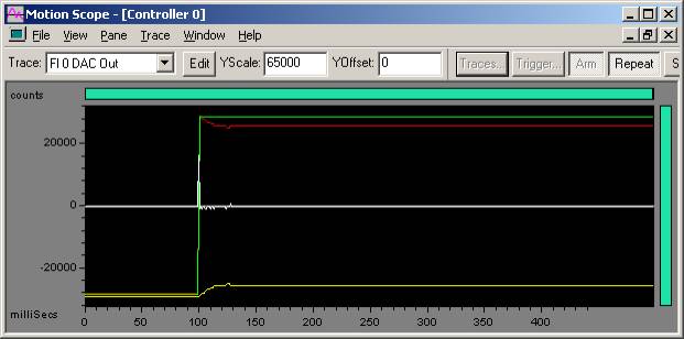
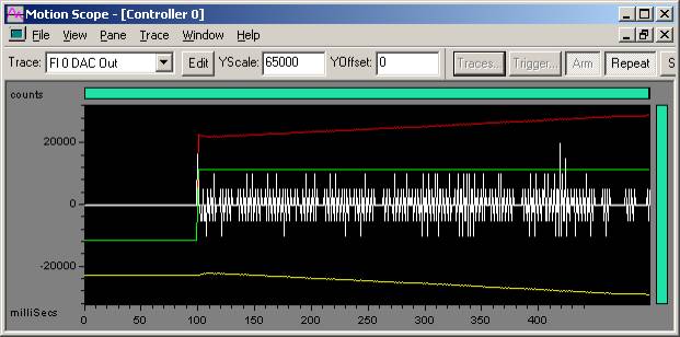
The Motion Scope screenshot below shows the following
traces:
- Commanded
Position - Green
- Actual Position
- Yellow
- Position
Error - Red
- DAC Output
- White
These traces help highlight the position step input (Commanded Position),
and the response (Actual Position). The Position Error is helpful to see
the difference in the commanded and actual position when the difference
is small. The DAC output shows the torque command to the motor. High frequency
oscillations are sometimes easier to see on the DAC signal than on the
position plots.
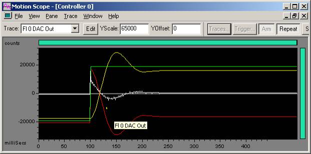
100 Count Step Commanded (Trapezoidal move, 1e10 accel, decel, vel)
Green - Commanded Position
Yellow - Actual Position
Red - Position Error
White - DAC Output
GOAL: To find the largest Kd value that can be used to command a step without getting any oscillation and then turn down Kd to a fixed amount (approx. 1/3 of the limit value).
It is best to start with a small Kd value like 1.0.
After commanding a step, look and listen for oscillation.
If you can see oscillation in Motion Scope or hear/see an objectionable
oscillation from the motor, turn Kd down and repeat.
If you do NOT notice any oscillation, turn Kd up and repeat.
Stop adjusting Kd once you've found the largest Kd value that you can use to command a step without getting any oscillation.
After you find this limit Kd value, turn it down a fixed amount. Setting Kd to 1/3 of the limit value is a safe place to start. You can try turning Kd down if you need more performance. Keep in mind that the less you turn down Kd, the less stable your system will be. At some point, if Kd is too large, you will get oscillation (buzzing, humming, etc). Remember, if you are tuning a machine for a production release, you can actually decrease the stability of the machine if the Kd is too large. It is recommended that you do not push Kd too far and allow yourself a buffer for safety and stability reasons.
It is often difficult to visibly see small and high frequency oscillations. It is usually easier to see oscillations on DAC output plots. Remember, the goal is to find the high-end limitation of Kd, not to find the most accurate motion.
A Trust TA 9000 was used to generate the following examples, unless otherwise noted. (http://www.trustautomation.com)
Acceptable motion on 100 count step move
(No objectionable audible noise on move and no audible noise when move
is settled)
Green - Commanded Position
Yellow - Actual Position
Red - Position Error
White - DAC Output
Kd = 2000
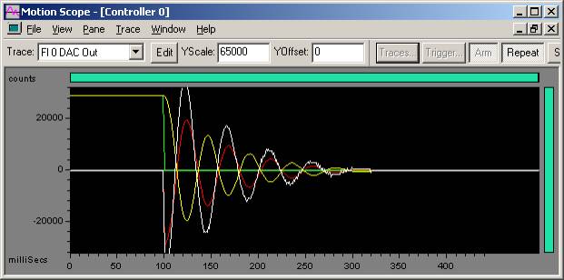
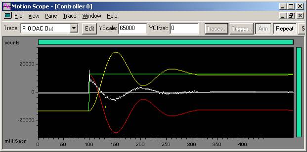
Excessive oscillation on 100 count step move
Green - Commanded Position
Yellow - Actual Position
Red - Position Error
White - DAC Output
Kd = 7000
In the plot above, when Kd = 7000, instability is found. When Kd > 6000, it results in audible noise and an erratic plot in Motion Scope.
Turn down Kd by 2/3 (6000 / 3 = 2000) and continue to Step 2 and tune Kp.
GOAL: To turn up Kp until there is half the overshoot of a step command.
Once you have tuned Kd, start to tune Kp. Turn up Kp until you get an overshoot of 50% of the specified step command. For example, if you command a 100 count step, a 50% overshoot means the peak actual position value is 150 counts. The 50% overshoot is a simple, repeatable measure of PID loop stability. Since your overshoot will automatically get larger when you tune Ki, this will provide some tuning flexibility.
In the plot above, the yellow trace (actual position) shows a 50% overshoot.
We now start with a Kp = 500.
Excessive oscillation on 100 count step move
Green - Commanded Position
Yellow - Actual Position
Red - Position Error
White - DAC Output
Kp = 500
Kd = 2000
Acceptable overshoot (26%) on 100 count step move
Green - Commanded Position
Yellow - Actual Position
Red - Position Error
White - DAC Output
Kp = 100
Kd = 2000
Once you have tuned Kp, start to tune Ki. Set ImaxMoving
and ImaxRest to the same value as Output Limit. In this case Output Limit
is 32767.
ImaxMoving
= ImaxRest = Output Limit = 32767
Ki is the last closed loop parameter, so we will want to turn up Ki until we get the specified overshoot. Turning up Ki will close the steady state error.
Acceptable overshoot (50%) on 100 count step move
Green - Commanded Position
Yellow - Actual Position
Red - Position Error
White - DAC Output
Ki = 0.43
Kp = 100
Kd = 2000
In a PID system, the proportional (Kp), derivative (Kd), and integral (Ki) terms all contribute to the total controller output (the three terms are added together). When a system oscillates at low frequency (the frequency varies, but is often a few Hertz lower), the integral term is likely the term that is oscillating. Kp and Kd are along for the ride are not affected. In an effort to control an oscillation due to the integral term, we can limit how much it contributes to the controller output. We limit the maximum contribution of the integral term while the stage is at rest with IMaxRest. We limit the maximum contribution of the integral term during a motion with IMaxLimit. There are several ways you can set these limits:
Full integral effect always - By setting IMaxRest and IMaxLimit equal to Output Limit, you will have no effective limit on the integral term. (IMaxRest = IMaxLimit = Output Limit)
Full integral at rest - Some systems may already
cause enough disturbances when set in motion. The integral will simply
make things worse by trying to compensate for the disturbances. If an
integral term is still needed to close steady state error, setting IMaxLimit
to zero and IMaxRest equal to Output Limit will turn off the integral
during motion, thereby enhancing stability.
To close steady state error when in motion,
(Integral is ON)
IMaxLimit
= 0
IMaxRest =
Output Limit
To close steady state
error when at rest, (Integral is OFF)
Half integral limit - It is possible to tune a stage so that it visually appears stable when in reality it is very unstable and may result in violent oscillation when the stage is grossly disturbed (ex: some large external force jars the stage). This is likely the result of an oscillating integral. By setting the integral limit to far less than the Output limit, integral oscillation can be damped out by the proportional and derivative terms. This is why it is important to set the integral limit to be larger than what is typically used during normally operation while also making sure that it is still significantly less than the output limit. It is often good to start with half of the output limit.
| | | Copyright © 2001-2021 Motion Engineering |
