1. Sensor Verification
When tuning a servo system for the first time, you should
verify that your feedback sensor is working properly. Here are a few simple
tests for sensor verification.
| |
- With the amplifiers disabled, physically move the stage in both
directions. You should be able to verify (MoCon->Motor Summary)
that the encoders read positive when you move the stage in the
positive direction and negative in the negative direction. If
you have a faulty encoder or encoder wiring, you may see no motion,
a flickering single count motion, or motion in a single direction,
regardless of which way you push the stage.
- If you get motion
in the opposite direction than the direction you
intended, reverse the A and B phases of the encoder wiring.
- If you get flickering
motion, or motion in one only direction, check
your encoder and encoder wiring.
- Next, verify that the command signal (DAC) and the encoders
are read in a consistent direction.
- Make sure the amp is enabled.
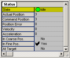
- First, clear any errors that might have occurred. See Error Limit and Limit Switch Errors. After all errors have been cleared, you should be able to verify that the states are cleared (Motion Console
 Axis Summary Axis Summary  Status tab Status tab  State). If there are no errors, the State is Idle. State). If there are no errors, the State is Idle.
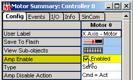
- Then enable amplifiers (Motion Console
 Motor Summary Motor Summary  Config tab Config tab  Amp Enable). Amp Enable).
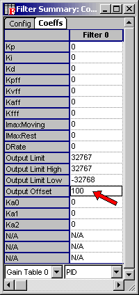
- With the PID tuning parameters
set to zero, add some offset (Motion Console
 Filter Summary Filter Summary  Coeffs tab Coeffs tab  Output Offset) until you see some stage motion (Motion Console Output Offset) until you see some stage motion (Motion Console  Axis Summary Axis Summary  Status tab ). Be sure to do this in both directions by setting
a positive and negative offset. Look for a positive motion on
a positive offset and a negative motion on a negative offset. Status tab ). Be sure to do this in both directions by setting
a positive and negative offset. Look for a positive motion on
a positive offset and a negative motion on a negative offset.
- If the motion is
in the wrong direction, reverse the positive and negative
DAC lines going into the amplifier.
- Alternatively, you
can also reverse the A and B phases of the encoder
wiring. But be careful, because the actual motion will go in the opposite
direction than is intended, although it will still be under servo
control.
|
| |
|
An example of using an offset to check if the encoder
and DACs have the same polarity: Set the P, I, D, and Ouput Offset to
zero. Note the actual position of the motor. Start increasing the motor
output a little at a time until you see some motor movement in Motion
Console. Remember that you are looking for the direction of travel (positive/negative).
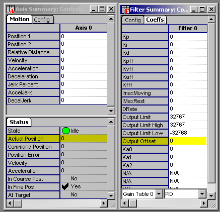
Actual Position is at zero
Output Offset is zero
A small Output Offset of 500 (out of +/-
32767) results in a small move of 31 counts in a positive direction. However,
we are not concerned with the size of the motion, but rather the direction
of the move. Since we entered a positive output offset and got a positive
motion (from 0 counts to 31 counts), the encoders are working properly.
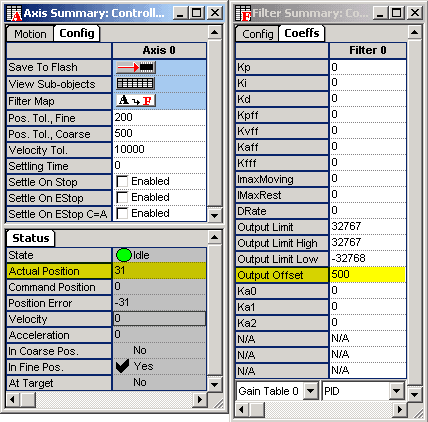
Actual Position = 31
Output Offset = 500
The actual position increased with a positive
Output Offset.
Before calling this procedure finished,
let's make sure that the opposite offset causes an opposite motion.
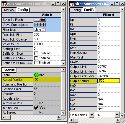
Actual Position = – 55
Output Offset = – 500
The actual position decreased with negative
Output Offset.
We can see that a negative Output Offset
(– 500) caused a negative motion (from 31 counts to – 55 counts).
If you do see motion in one direction,
but not the other, check your amplifier and encoder wiring.
Error Handling and Safety
The XMP has several simple ways of detecting servo errors
and how to make the appropriate changes. These are relatively simple tests
that can help prevent damage to equipment. Here are simple descriptions
of each type of error.
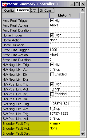
Limit Switch Configuration
A common mistake is to NOT hook up the limit switches.
If your servo has a limited travel, you need limit switches. The various
limit switches can be found in the Motor Summary  Events tab. During servo tuning, it is easy to unknowingly use an unsafe
number and have a stage runaway.
| |
- Before tuning a servo, it is recommend that you set up the error
limit switch action to "Abort." This will effectively
turn off the drive when an error limit is encountered.
- Make sure that the polarity of the limit switch is set so that
the limit switch is considered triggered if you disconnect it.
This will protect the stage if there is a limit switch cable failure.
- Normally the limit switch duration is set to zero. This means
that if a limit switch has been met, the limit switch action (Abort)
will immediately be acted upon. You can also type in a non-zero
value into the field to designate that a lag of x sec must
elapse before the the limit switch action is acted upon. This
is sometimes useful with noisy switches. However, if you have
a runaway state, you usually want action (an Abort) to be taken
immediately.
NOTE: There are separate
limit switch configurations for both the positive and negative direction.
|
Software Limit Configuration
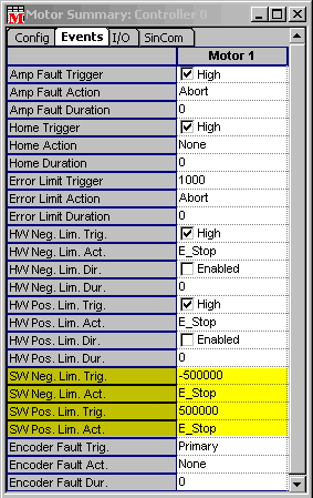
The Software Limit Configuration is very similar to
the limit switch configuration, except that the "switch" is just a position
(in counts) read by the encoder. Instead of having a polarity, the software
limit has a trigger value. This is the position at which the software
limit will take effect. For instance, if you want the servo to perform
an E-Stop when it reaches 500,000 counts, you should set the Limit Switch
Configuration to be 500,000.
NOTE: There is a separate software limit for
both the positive and negative direction.
Position Error Configuration
The position error is sometimes referred to as following
error. The position error limit will perform an action if the position
error exceeds a preset value.
| |
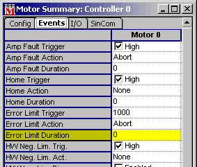
- Set the value in the Error Limit Trigger. Typically you would
set the position error to the smallest value that you are confident
you will never see in normal operation.
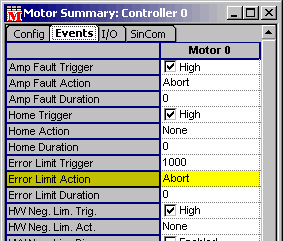
- Set the Error Limit Action to ABORT. If you get an error limit
event, your motion is by definition uncontrolled. If you do not
abort the motor (turning the drive off), you will be trying to
servo with an axis that is not servoing correctly in the first
place. In stepper motor configurations without encoders, set the
error limit action to NONE. Without feedback, the error limit
has no real meaning.
- Normally the position error duration is set to 0. This means
that the position error will be acted on as soon as it is detected.
If the error limit duration is a non zero value, the position
error will not be acted on until the position error has existed
continuously for duration seconds.
|
Amp Enable Configuration
A common mistake when tuning a servo is thinking that
you can manually turn off the amp if something goes wrong. But, most servo
stages are fast enough to hurt themselves in a fraction of a second. Therefore,
let the controller do its job and allow it to turn the drive off if there
is a problem. That is why it is important to wire up the stage correctly
from the start, otherwise the controller can't protect the stage.
| |
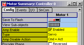
- Make sure that the polarity of the amp enable is set so that
the amp is disabled if you disconnect the amp enable cable (does
not apply for SynqNet drives). If you have an amp enable cable
failure, this will make sure you detect the error and shut off
the amp.
|
Amp Fault Action
The XMP can take action on an Amp Fault. Keep in mind
that some amps indicate a fault condition when they are merely disabled.
In cases like this, it is more complicated to turn on an amplifier.
| |
- Make sure that the polarity of the amp fault is set so that
the amp fault is triggered if you disconnect the amp fault cable
(does not apply for SynqNet drives). If you have an amp fault
cable failure, this will make sure you detect the error.
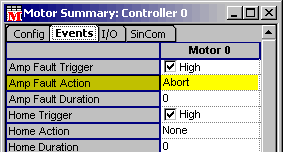
- Set the Amp Fault Action to ABORT. If you get an Amp Fault Event,
you want to stop attempting to servo and disable the amp. In all
likelyhood, the amp has disabled itself at this point, and further
commanded motion has little meaning. If you do not abort the motor
(turning the drive off), you will be trying to servo with an axis
that isn't servoing correctly in the first place.
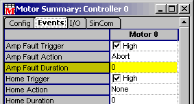
- Normally the amp fault error duration is set to 0. This means
that the amp fault error will be acted on as soon as it is detected.
If the amp fault error duration is a non zero value, the amp fault
error will not be acted on until the amp fault error has existed
continuously for the specified duration (in seconds).
|
Encoder Fault Action
If you have an encoder fault, it is likely that you
will get a runaway servo. The XMP has the ability to detect broken encoder
wire conditions and invalid encoder states. This applies to some, but
not all SynqNet drives. The XMP encoder receivers have a termination resistor
that will pull the positive and negative halves of the encoder signals
together if a wire breaks. The invalid state occurs when the A and B phases
of the encoder change at the same time. This makes the encoder position
uncertain. An Encoder Fault is the general term and can be caused by two
conditions: Broken Wire and Invalid State.
| |
- Set the encoder fault action like the other errors. We recommend
using an abort action because the servo feedback is an unknown
when you get an encoder fault.
- The trigger can be set to trigger off of an Invalid State, Broken
Wire, or Absolute Encoder error. Absolute encoder errors are not
covered here.
- Encoder Faults cannot be cleared. The controller must be reset.
An encoder fault is a serious condition, and should be looked
into before continuing.
|
|
